This guide provides practical advice on managing the risks of using machinery in the workplace.
Download:
Key points
- Machinery is a major cause of injury and death in New Zealand workplaces.
- Designers, manufacturers, importers and suppliers of plant have duties to make sure that the machinery is safe before it goes into use.
- Guarding is an important control in isolating a hazard, but it should always be secondary to eliminating the hazard.
1.0 About this good practice guide
1.1 What are these guidelines about?
These guidelines provide advice on how to manage the health and safety risks around the use of machinery in the workplace. They can help persons conducting a business or undertaking (PCBUs) meet their duties under the Health and Safety at Work Act 2015 (HSWA).
1.2 Who should read these guidelines?
These guidelines are for any PCBU involved in the use of machinery. This includes PCBUs that:
- use machinery for processing or manufacturing
- design, manufacture or supply the machinery
- install, inspect and maintain the machinery
- modify and/or decommission the machinery.
These guidelines:
- can help PCBUs meet their duties under the Health and Safety at Work Act 2015 (HSWA) and other relevant legislation
- give examples of good practice.
1.3 The use of Australian New Zealand Standard AS/NZS 4024:2019
You will see references to AS/NZS 4024:2019 throughout this guidance. This is the standard that gives the current state of knowledge for the safeguarding of machinery and plant.
PCBUs should refer to AS/NZS 4024:2019 as the primary standard against which to benchmark. This applies to all duty holders involved in the use of machinery including design, manufacture, supply, installation and users.
PCBUs can work to other standards but need to show that they can reach the same level of safety, or better, in the circumstances in which the standards are used.
The AS/NZS 4024:2019 standards provide guidance only. Compliance with them does not guarantee compliance with HSWA and the relevant regulations.
1.4 What things mean: terms used in this guidance
| Term | Meaning in this document |
|---|---|
| 'you'/'your' | Refers to the PCBU involved in the use of machinery. |
| 'must' | Where 'must' is used the action, task or duty is a legal requirement under HSWA or regulations.
You have to comply with the requirement |
| 'should', 'make sure', 'check', 'needs to' or similar wording |
This wording indicates how WorkSafe New Zealand expects certain health and safety risks to be managed. It is not mandatory to follow these expectations, and you may adopt other practices. But these practices need to provide a level of health and safety as good as, or better than the standard in this guidance. |
Table 1: Terms used in this guidance
See Appendix 1: Glossary for further terms.
2.0 Who is responsible for what?
2.1 Who are duty holders?
HSWA sets out the work health and safety duties that duty holders must comply with.
There are four types of duty holder under HSWA:
- a person conducting a business or undertaking (PCBU)
- an officer
- a worker
- an ‘other person’ at the workplace
Examples of what duty holders are, and their duties can be found in Appendix 2: Duty holders and certain duties
2.2 Who has responsibility to make sure that machinery is safe to use?
Designers, manufacturers, suppliers and businesses using machinery all have duties to make sure that machinery is safe to use.
Designers, manufacturers and suppliers have responsibilities known as upstream duties.
An upstream PCBU is a business that:
- designs plant, substances, or structures
- manufactures plant, substances, or structures
- imports plant, substances, or structures
- supplies plant, substances, or structures
- installs, constructs or commissions plant or structures.
Upstream businesses are in a strong position to eliminate or minimise risk.
They can influence and sometimes eliminate health and safety risks through designing, manufacturing, importing or supplying products that are safe for the end user.
For more information on these responsibilities see Appendix 3: Upstream duties – who is responsible for what and when
The responsibilities of PCBUs who supply plant do not apply to the sale of plant that is second-hand. For more information on buying second-hand plant, see Section 11: Buying second-hand or from overseas
3.0 Managing risk when using machinery in the workplace
3.1 Introduction to risk management
Machinery in the workplace presents many risks to workers and other people’s health and safety.
You must manage these risks so far as is reasonably practicable.
As good practice you should:
- identify hazards and work out what risks they present
- put in place control measures to eliminate or minimise those risks
- talk to and engage with your workers and their representatives throughout the risk management process.
For more information on risk management, see How to manage work risks
4.0 Identify hazards
The first step is to identify hazards – anything that could injure or harm someone.
Do a workplace inspection to identify all machinery used.
You can identify hazards by:
- Physical inspections. Inspect the machinery and assess where someone could get injured or caught in the machinery.
- Conversation and consultation. Talk with your workers, the people who use the machines and the people who work around the machines. They will know better than anyone what could go wrong. They will also know how the work is done – the short-cuts and different processes they may use to get a job done.
- Task analysis. Look at how each task is carried out and the hazards involved in the task. This should include what happens when there is a blockage, or the machine needs cleaning or maintenance.
- Review incident and injury records. Identify hazards and causes of harm from what has happened before, and the things that nearly happened (the near misses). Also look at what is happening in other businesses in your industry – industry groups and organisations are good for this.
4.1 The following checklist may be useful for identifying hazards
Safe use of machinery checklist
| Check: present status, recommendations, useful information |
| Guarding requirements |
|---|
| Do guards stop workers touching dangerous moving parts? |
| Are guards firmly secured and not easily removable? |
| Do guards stop objects falling into the moving parts or from exploding out of the machine? |
| Do guards allow safe, comfortable and easy use of the machine? |
| Can the machine be maintained without removing the guard? |
| Can the existing guards be improved in a practical manner? |
| Are there safe procedures in place and a way to shut down the machine if something out of the ordinary happens, like a blockage? |
| Are there procedures to test or check 'unseen' guards such as light barriers and presence-sensing systems? Can someone tell if they are operational and, if so, how? |
| Issues or concerns? |
| Mechanical hazards: point of operation |
| Is a guard on the machine at every point of operation where there is a hazard? |
| Does the guard keep the operator's hands, fingers and body out of the danger area? |
| Have the guards been tampered with or removed? |
| Is there a more practical or better guard? |
| How can point of operation hazards be removed? |
| Are the tools used for placing and removing material the right length, type and size to keep an operator's hands out of the machine? |
| Issues or concerns? |
| Operator controls |
| Are start and stop controls in easy reach of the operator? |
| If there is more than one operator station, are separate controls placed where operators can see the entire operation? |
| Are controls, including foot controls, guarded against being turned on accidentally? |
| Are controls labelled clearly with their function? |
| Are controls similar in type and arrangement to other similar machines in the plant? |
| Are emergency stop controls easily reached and clearly identified? |
| Is the machine wired so it has to be manually re-started if power is cut and then restored? |
| Issues or concerns? |
| Mechanical hazards: power transmission |
| Are gears, sprockets, pulleys or flywheels guarded? |
| Are there any exposed belts or chain drives? |
| Are there any exposed sets, key ways, collars, etc? |
| Are all hazardous moving parts guarded, including auxiliary parts? |
| Are start and stop controls in easy reach of the operator? |
| If there is more than one operator, are there separate controls? |
| Issues or concerns? |
| Other hazards |
| Are other hazards like noise, fumes and vibrations identified and managed? |
| Have special guards, enclosures, or personal protective equipment been provided to protect workers from exposure to hazardous substances? |
| Have hazards associated with layout, repetitive movements and workload been identified and managed? |
| Issues or concerns? |
| Electrical hazards |
| Does the machine require regular tagging and testing? If so, how often? |
| Are there loose conduit fittings? |
| Is the power supply correctly fused and protected? |
| Do workers occasionally get minor shocks while using any of the machines? |
| Issues or concerns? |
| Training and supervision |
| Are operators and skilled workers trained and competent to use the guards? |
Are production workers trained in:
|
| Are operators supervised by competent staff? |
| Have workers been trained in what to do if they notice guards that are damaged, missing or inadequate? |
| Issues or concerns? |
| Protective equipment and clothing |
| Is protective equipment and clothing needed? |
| Is it right for the job, in good condition, kept clean and stored when not in use? |
| Is the operator dressed safely for the job (no loose-fitting clothing or jewellery)? |
| Issues or concerns? |
| Machine maintenance, repair and cleaning |
| Do technicians, engineers or operators have up-to-date instructions on the machines they service or clean? |
| Do staff or contractors lock-out machines from all energy sources before starting repairs or cleaning? |
| Is the maintenance equipment properly guarded? |
| Where several maintenance staff are working on the same machine, are multiple lock-out devices used? |
| Is the machinery properly maintained and kept clean? |
| Issues or concerns? |
| Machinery set-up |
| Is all machinery securely placed and anchored to prevent tipping or other movement? |
| Is the machine laid out so it does not create hazards to operators or others in the workplace? |
| Is there enough clearance around and between machines to allow safe operation, set-up, servicing, material handling and waste removal? |
| Issues or concerns? |
Table 2: Checklist for identifying hazards
4.2 Machinery hazards
There is a number of types of hazards to consider when looking at the safe use of machinery. They include (but are not limited to):
- mechanical hazards
- ergonomic hazards
- chemicals and fumes
- exhaust (gases/fume/diesel) emissions from ICE
- organisational hazards
- electrical safety
- environmental and occupational hazards.
Each should be identified, their risks assessed and managed.
4.3 Mechanical hazards
There are many different mechanical hazards presented by machinery that can cause serious harm. These include:
- drawing in or trapping
- crushing
- impact
- shearing
- friction and abrasion
- entanglement
- cutting
- stabbing and puncturing.
For more explanation and examples, see Appendix 4: Mechanical hazards in machinery
4.4 Electrical safety of machinery
The wiring and fittings of machinery connected to the mains or electricity generating device must meet all legal requirements and must be installed by or under the supervision of an authorised or licensed electrician.
All tagging and testing should be carried out by a certified, professional third party in line with legal requirements and relevant standards.
All portable or handheld machinery that gets power from electricity should be used with an isolating transformer or residual current device, where needed. Get specific advice from an electrician or the electricity supplier on the best device to use.
4.5 Chemicals and fumes
Many chemicals used with machinery can harm workers. Assess all chemicals for hazardous health effects. Put appropriate controls in place to stop or control people's exposure. To monitor the environment or workers' health to make sure exposure to the chemicals is not affecting their health, consult a competent person such as an occupational hygienist.
For more information refer to the substance's safety data sheet, available from your supplier.
Control of airborne hazards – ventilation
Protect workers, so far as is reasonably practicable, from inhaling steam, fumes, dust and other airborne contaminants in the workplace. You can use ventilation, filtration and/or mechanical extraction. Remove any contaminants made as part of the work at the source.
Any mechanical extraction should pull contaminants away from workers' breathing zone, not through it.
If it is not reasonably practicable to completely remove or isolate the hazardous substance, you must minimise any risk of harm to the employee.
To minimise the risk, an employer can:
- monitor employees' exposure to the hazard
- monitor employees' health (with their informed consent)
- provide protective clothing and equipment (such as respirators) and make sure they are used.
4.6 Ergonomic hazards
Ergonomic hazards come about through the way the operator interacts with the machine.
Sometimes machinery is not always designed for how an operator should use the machine. For example, operators may have to overreach, reach above shoulder height, hold awkward postures, and use repetitive or forceful movements.
Having to work this way can cause damage to nerves, muscles and tendons.
Ergonomic hazards can cause serious harm to operators, but they do not need to. These hazards can be removed at the design stage. For more information, see WorkSafe's guidance Health and safety by design
Hazardous manual handling
By considering how and when a machine is used, you can reduce the risk of injury. This includes:
- How well the working environment is set up? Can operators safely reach frequently used displays, instruments or control panels while keeping correct posture?
- What type of machinery is used? Does the machinery expose anyone to too much vibration, noise or emissions or does it need physical force to work?
- How work is organised? How much work needs to be done? How urgent is the work? How many breaks do operators get? How long are the breaks?
- What physical demands are put on the person using the machinery? Is the work repetitive? Does it require awkward movements or postures? Does the operator have to work in extreme temperatures?
- Check whether tasks require repetitive movement or there is a risk of musculoskeletal injuries and gradual process disease.
Layout and design
Good layout makes guarding better at keeping people safe. Machines that are poorly placed or too close together can be unsafe, even if guarded.
When designing layout:
- avoid congestion points or worker movements near hazardous machinery
- make sure people can use, clean and maintain the machinery without being harmed
- make space for any waste materials to gather before they are cleared (they should not clutter walkways or work areas)
- note the movements of trucks, materials and people
- mark out walkways and create vehicle movement areas
- mark out 'no-go' areas, so people can stay away from dangerous machinery.
Check how close moving parts are to other machinery and fixtures in buildings.
Reach and guarding
The main point of machine guarding is to stop workers reaching past the guard into the machine. When deciding on the best way to guard a machine, consider how a worker uses and interacts with a machine (ergonomic principles).
You can find more information in Ergonomics of machine guarding
4.7 How work is organised
For machine guarding to work well, employers need to:
- understand how materials move through the site
- develop safe operating procedures on how to use machinery safely, including maintenance and cleaning
- train workers to work safely.
New technology, new machinery or changes to machinery can introduce new hazards.
At these times, always complete a hazard assessment and consult with workers.
Fatigue and shift-work
Fatigue is a hazard. PCBUs must take all reasonably practicable measures to minimise the risk of fatigue, such as when employees drive or use dangerous machinery.
Shift-work can be hazardous because it disrupts normal rest patterns. Employees need enough recovery time outside work so they can be safe and productive at work.
Along with enough sleep, breaks during work hours are important to maintain an employee's physical and mental well-being. For more information, see Fatigue quick guide
4.8 Environmental and occupational health hazards
When reviewing machinery for non-mechanical hazards, consider how the presence of machinery can affect the work environment.
A thorough hazard identification process should consider the effect environmental factors (such as lighting, heat, and cold) can have on workers when using machinery.
Working at height
People need a suitable work platform to reduce the risk of falling from machinery.
Working safely at height may need:
- fixed or permanently installed access platforms
- mobile elevating work platforms
- temporary platforms
- fall restraints.
For more information, see Working at height in New Zealand
Lighting
Make sure the work area is appropriately well lit. Poor lighting can be a hazard as can overlighting and reflected light. Sometimes the machine or guards can block normal lighting, so extra local light is needed. Also consider putting local lighting in maintenance areas that are poorly lit, such as inside some electrical compartments where electrical isolation is needed for access.
For more information refer to AS/NZS 1680.2.4 Interior lighting – Part 24: Industrial tasks and processes.
Noise
Employers must take all reasonably practicable steps to reduce any risk of harm to people from machinery noise.
Where this is not practicable, employers should isolate people from excessive noise including providing appropriate hearing protection as necessary. For more information on controlling noise, refer to Noise
Operating speeds and dangerous vibration
No machine should be driven or used at an unsafe speed. Where a designer or manufacturer recommends a working speed for a machine, do not operate any faster.
Maintain machines so there is no dangerous vibration when the machine is working or when moving parts and cutters are running.
For more information, see Vibration
Machinery stability and security
All machinery should be secured to the floor or other structure so that it cannot tip, become unstable or create any other hazards, unless it is designed to be portable.
Weight of guarding
Large machinery may need a lot of guarding, which may need to be removed for maintenance access.
Well-placed handles make removing, lifting and handling easier and reduce the risk of manual handling injuries.
Where practical, use cranes or other lifting devices to move heavy guards.
Access hazards
Operators and employees need safe access into, on and around machinery. Workers need a stable work platform that is right for the work they need to do. The operator should be able to keep good posture while working. The platform should provide a sure footing, a safe working environment, and prevent falls at height.
When designing safe access to machinery, think about:
- Who will be working on or around the machinery?
- Do people need to work in enclosed areas where the atmosphere could be harmful (such as pits, tanks or storage vessels)?
- What equipment or materials need to be carried to do the job?
- Where and when is access needed to use, maintain and clean the machine?
- How will people get safe access (such as from a walkway, gantry, elevated work platform, ladder)?
- What work will be carried out with the machine?
- Will people be near or exposed to any mechanical or non-mechanical hazards when they access the machine?
- Has consultation occurred with employees or contractors about how they intend to gain access, and what equipment and work platform or structure is best suited for the intended task?
Confined space
Larger machinery and equipment can have enclosed areas that are difficult to get to. In confined spaces, oxygen levels may be low or there may be harmful levels of gas, vapour or dust. You need to consider how you will manage those risks.
For more information, refer to the AS/NZS 2865 Confined spaces.
Housekeeping
Mess can cause slips, trips and falls. Avoid injuries by:
- keeping work areas, walkways and other access paths clear and clean
- clearly marking walkways and no-go areas
- preventing spills, which can cause slips.
Design machinery and work processes to minimise oil loss or spillage. Clean up spills as soon as possible and avoid any oily residues on the floor. Consider putting in an anti-slip floor.
Operational hazards
As well as the hazards associated with the normal running of the machine, there are also hazards associated with cleaning, maintenance and repair, along with irregular hazards.
To keep people safe during inspections, cleaning, repairs, maintenance and emergencies:
- use isolation procedures whenever people need to enter the danger area around machinery for maintenance and repair
- make sure workers understand cleaning, repair, maintenance and emergency procedures
- put in place a regular inspection regime to identify any problems with machinery and guards
- identify and assess any other hazards specific to inspections, cleaning, repair, maintenance and emergencies
- take special precautions when workers cannot be seen or where there are multiple operating switches
- if dangerous parts need to move while a guard is open (for example: setting, fault finding, or maintenance), use safe operating procedures (such as speed as slow as practical, and two-hand hold-to-run inching controls with pendant) to minimise hazards and the risk of injury.
All PCBUs and workers involved with machinery should read, understand and use the practices set out in the Keeping workers safe when servicing machinery quick guide, particularly the practices around 'lock out/tag out'.
5.0 Assess the risk
Once you have identified the hazards, you will need to work out what risks they present.
A risk assessment looks at:
- how likely a hazard is to cause harm
- how serious the harm could be and how badly someone could be hurt
- how many people are likely to be exposed to the risk, and
- do their skills or experience influence the likelihood of the harm occurring.
Risks that have the potential for causing serious injury or death, or chronic ill-health have priority.
Just because a risk has lower likelihood of occurring or lower potential for harm does not mean that it can be ignored.
A risk assessment should cover:
- where, which and how many workers could be injured or harmed
- how often this is likely to occur
- how serious any injuries might be.
For example, if you were looking at hazards from moving, rotating or reciprocating machinery, you would first assess how likely it is that a worker could get caught, entangled or nipped, and then determine how serious any injury might be.
Risk factors to consider during the risk assessment include:
- visibility – how easy is it to see the hazard?
- orientation – for example, a feed screw that is low and horizontal could entangle hair, ties and jewellery. A screw in a different place or angle would pose a different risk.
- anticipated work practices, including less obvious ones such as:
- maintenance, inspection, repair and cleaning practices (for example, a screw conveyor is behind closed panels, but when it jams, a worker may open the panel and stick their hand in)
- infrequent or one-off tasks required on the machine.
When assessing the risk, take into consideration:
- whether the danger zone can be reached
- the likelihood of a worker putting fingers, hands, arms, feet or legs into places where they do not normally go when the machine is running.
5.1 Adequate information, knowledge and experience
The people doing risk assessments need the right information, knowledge and experience of the work environment and work processes.
It is important to talk to workers and health and safety representatives, who can advise on the hazards and risks for different machinery. They will also have their own knowledge of how work is carried out.
The AS/NZS 4024 Safety of machinery series has more information on risk assessment factors and methodology.
6.0 Manage the risk
You must eliminate risks so far as is reasonably practicable.
If you cannot eliminate the risk, you must minimise it so far as is reasonably practicable.
Use the hierarchy of controls to minimise risk. These operate from the highest level of protection to the lowest.
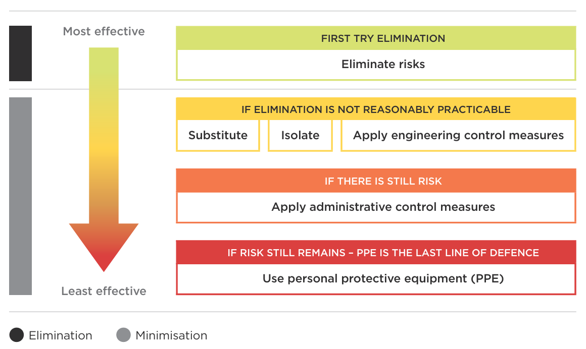
A hierarchy diagram divided into two main sections: Elimination and Minimisation, arranged from most effective at the top to least effective at the bottom.
At the top, under 'First try elimination': Eliminate risks.
Below that, under 'If elimination is not reasonably practicable', there are three control measures shown side by side:
Substitute, isolate, and apply engineering control measures.
Below those, under 'If there is still a risk': Apply administrative control measures.
At the bottom, under 'If risk still remains – PPE is the last line of defence': Use personal protective equipment.
End of text alternative.
6.1 Eliminate (get rid of the hazard)
Change or redesign the way you do a job so that the hazard is removed or eliminated. For example:
- design or modify the machine to eliminate the hazard
- eliminate human interaction for example by automating handling
- get rid of pinch points
6.2 Minimise
If it is not practicable to eliminate or isolate the hazard, then the likelihood of it causing harm must be minimised.
Minimising a hazard can stop injuries, but it is the least effective option because it relies more on human behaviour, maintenance programmes and supervision.
Minimising can include the following:
6.3 Substitute (replace)
Replace a process or a material with a less hazardous one.
6.4 Isolate (prevent access)
Use physical control measures to keep people away from the hazard. For example:
- fixed guard
- interlock guard
- interlock distance bars
- failsafe interlocking.
Other engineering control measures to minimise a hazard could include:
- presence sensing devices
- light curtains
- computer or AI warnings
- light beacons and strobe lights
- lock-out systems.
Administrative controls are procedures to make sure the work is done safely. These could include:
- signage
- training
- supervision
- safe operating procedures
- safe system of work.
Personal protective equipment (PPE) is the last line of defence. PPE is only used when other control measures alone cannot adequately manage the risk.
6.5 Monitoring control measures
Control measures are not 'set and forget'. Situations change as will your business and processes. It is important that you monitor your control measures to make sure they are working.
Engage with your workers and their representatives to see if the control measures are eliminating or minimising work risks.
Check incident reports and near miss reports (and encourage your workers to report incidents and near misses).
Carry out inspections of the work and the site(s), paying particular attention to known risks and risk control measures.
Monitor regularly. Make sure all policies, processes and systems have a scheduled date for a review or audit to check that they are being followed and are still fit-for-purpose.
Acting on lessons learnt
If you find that your control measures are not working effectively, or if your workers have suggestions for improving them, take action.
If there is an incident or near-miss, investigate. Find out what caused it and what needs to change to make sure it does not happen again. If need be, go through the risk management steps again and look at how and where you might adapt or improve control measures.
Look outside your own business. Observe what is happening in the industry from the industry association and other engineering/machinery/manufacturing operations. Look internationally, too. There are always things that you can learn and improve to make for better health and safety.
6.6 A quick summary of risk assessment
Follow these steps:
- identify what could go wrong
- identify who might be affected and how they might be harmed
- identify controls that are needed to stop it going wrong
- show that any remaining risk after all reasonable controls are in place is low enough to be acceptable
- record all your findings and keep these records
- tell everyone what they need to know and do
- make sure it all gets done
- ensure that if anything changes, you check you have got the right things in place. If not, stop the activity and review what is needed.
7.0 Use of guarding to isolate
This section looks at how guarding is best used to isolate a hazard.
Guarding is an important control in isolating a hazard, but it should always be secondary to eliminating the hazard.
7.1 Types of guards that isolate the hazard
Fixed guards
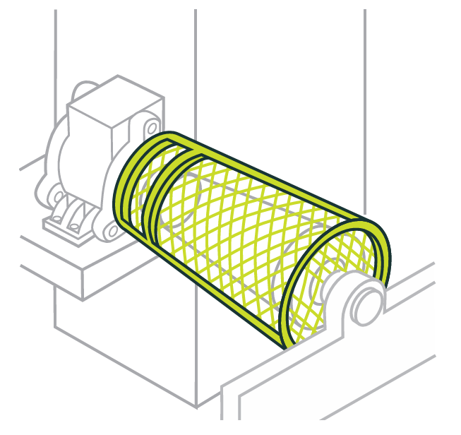
Fixed guards are physical barriers that keep people out of dangerous areas during normal use, maintenance or cleaning. The guard design will be influenced by the need to adjust drive belts and transmission chains and other factors.
Barriers or fences held securely in place with fasteners or other suitable devices can stop access to dangerous areas.
Fixed guards can be:
- permanent – welded into or part of the body of the machine
- removable – but they can only be removed when the machine is stopped with tools that are not easily available to the operators.
Do not use wing nuts, wedge insets or anything that can be undone with the fingers.
Machine guards should be made of substantial materials (such as sheet steel, wire mesh) that cannot be easily damaged.
Interlocked guards
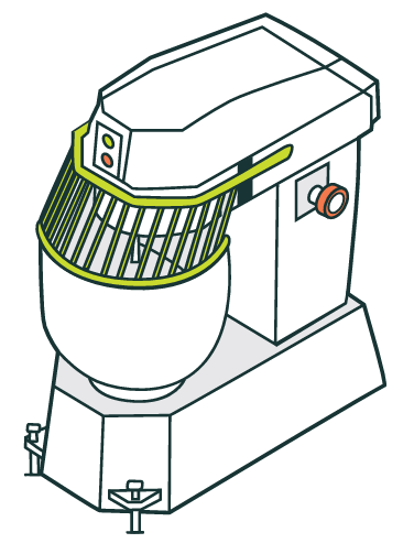
Interlocked guards work by cutting power to the machine when the guard is opened. They are a good guard to use when a machine needs to be accessed often.
If parts keep moving when the machine is not working, you need to use a type of guard that cannot be opened until all parts have stopped moving, or fit devices that stop the machinery. Any brakes fitted to machinery need to be well maintained.
Use a suitable anti-freefall device with interlocked rise and fall guards on machine tools that can injure if the guards freefall under gravity.
Power-operated guards should take a minimum of force to work so they do not create a trapping hazard. Where it is not possible to reduce the closing force of a guard, fit a safety trip device to the leading edge of the guard that will stop and reverse the guard if the guard contacts an object, like a hand.
When using barriers such as fences, there is a danger that machines can start when someone is near them, such as when an interlocked door accidentally closes and the machine re-starts. To stop an interlock door closing accidentally, fit devices such as a spring or gravity latch, which need a deliberate action from someone to close the door.
Interlocked guards should be designed so that any failure or loss of power does not expose people to danger. The design also needs to take into account the possibility of someone being inside the area enclosed by the guard when someone tries to start the machine.
Only after doing a risk assessment can you know what type of safety device to install with the guard, and the level of integrity of the related control circuitry. For more information, see AS/NZS 4024.1501 and AS/NZS 4024.1503.
Safe by position
Safe by position relies on putting dangerous machinery parts out of reach of people. This method needs policies and practices in place to make sure that the protection is not compromised as people can often use ladders, furniture or parts of the machine to reach the hazard.
When deciding how far away to put dangerous machinery, also consider how maintenance people will get access, such as by ladder, scaffold or mobile elevating work platform.
When putting controls in place to stop people reaching a hazard, always consider that it is human nature to try and defeat an obstacle. Make sure your controls are not easily defeatable.
Trip guards
When other guarding methods are not practical, you can use trip guards. A trip guard is designed to cut the power if someone reaches into a dangerous part of a machine.
However, if this system fails, there is no physical barrier to stop people touching dangerous parts. All safety trip guards should be hardwired to the machine control and power brake systems.
7.2 Ergonomics and making sure workers cannot reach past machine guarding
Ergonomic principles cover how a worker uses and works with a machine. Making sure workers cannot reach past the guarding into the machine is a key part of machine guarding and isolating the people from hazards.
Typical ergonomic principles include:
- the nature of operator postures and movements
- the ease of physical operation
- the effects of noise and temperature
- the lighting environment
- the clarity and location of manual controls
- the design of dials, markings and displays.
| Part of body | Gap (maximum size of any aperture or openings in the machinery) | Minimum separation distance from danger zone |
|---|---|---|
| Fingertip | 4 mm | 2 mm |
| Finger | 6 mm | 20 mm |
| Hand | 12 mm | 120 mm |
| Arm | 40 mm | 850 mm |
| Arm (reaching above head) | 2,700 mm |
Table 3: Gaps and separation distances in design and positioning of guards
Reach is limited by the length of arms, fingers and hands, legs and feet. The distance a person can reach sets the minimum height for some guards or the minimum distance of barriers from the hazard.
The average size and reach of humans are used to set design criteria. There will be some people – the very tall or very slender – whose size means they are not fully protected by the standard measurements given. More information can be found here:
- AS/NZS 4024.1801 Safety Distances to Prevent Danger Zones Being Reached by the Upper Limbs
- AS/NZS 4024.1802 Safety Distances and Safety Gaps – Safety Distances to Prevent Danger Zones Being Reached by the Lower Limbs.
Danger zone separation distances
Use Table 3 to assess the risk in machinery and the design and positioning of guards. The minimum separation distances are based on people with long arms, hands and fingers. The gaps are based on people (over 14 years old) with small fingers and hands.
More information is in AS/NZS 4024.1801 Safety of Machinery: Part 1801: Safety Distances to Prevent Danger Zones Being Reached by the Upper Limbs.
The anthropometric data used in this standard was based on information available when the standard was developed. Better sources may become available. If your workforce is significantly different from the general population, you may need to take your own measurements.
If someone can fit an arm through a gap, the hazard assessment should also consider any smaller openings inside the machinery.
If the arm can be bent at:
- the elbow – the minimum separation distance from the elbow to any danger zone should be 550 mm
- the wrist – the minimum separation distance from the wrist to any danger zone should be 230 mm.
Location of distance guards
Distance guards should be at least 1400 mm tall and at least 900 mm away from the danger zone; further or higher if there is a projectile hazard.
If the guard is between 1000 mm and 1600 mm tall, it should be at least 1500 mm away from the danger zone. No guards should be less than 1000 mm high.
Guards less than 1400 mm should only be used when there are additional protective measures.
8.0 Use of controls to minimise
This section details the type of guarding and control options that will minimise the risk of harm occurring.
These controls should only be used if the hazard cannot be eliminated or isolated. These guarding options generally protect more than one person and are called group controls.
8.1 Power controls
The power control is the device on a machine that controls the flow of energy to the prime mover. This energy source may be:
- electricity
- hydraulic oil under pressure
- compressed gas.
The power control should be able to stop the flow from all energy sources.
Interlocks and labels should clearly indicate where there is more than one energy source and stop all sources of energy to the prime movers.
The power controls should be:
- able to open all energy sources (such as all phases of a three-phase electrical supply)
- built and shrouded so the machine cannot be started accidentally
- clearly identified, with labels giving information on when and how to start the machine
- convenient to use and placed using sound ergonomic principles away from dangerous parts
- fail-safe, in case the energy supply is cut
- lockable in the off position when a person at the controls might not be able to see staff working on the machine
- showing the direction of the movement of the controls, which match up to the motion of the moving parts
- unable to be locked out in the on position
- unable to indicate off position if it is in fact in the on position.
Hydraulic controls should be either dead-man or hold-to-run type with anti-tie down, so that if the control is released the machine stops moving.
When a machine's power falls to a low level or stops completely, exposing parts of the machine, this can create a significant hazard when the power is restored. The machine should need the deliberate operation of the power control to start the dangerous parts.
Photoelectric safety devices
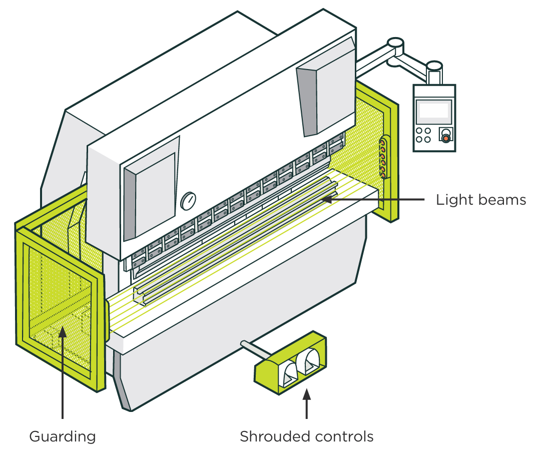
Photoelectric safety devices use light beams that stop machines working when the light beam is broken. This method is often used when fixed or interlocked mechanical guards are not practical. However, if the system fails, there is no physical barrier to stop people being exposed to the hazard. Photoelectric devices can be set to control how much anyone can enter a restricted space, such as a hand but not the arm, or an arm but not the body.
Single light beams are not normally suitable because people can reach around the light beam and access the hazard. You can use multiple light beams so there are no gaps that people can reach through, around, under or over. When any of the beams are broken, the power is cut.
Consider carefully what distance a light beam curtain is placed from the hazard. If it is too close, someone can reach through the light curtain into danger faster than the control system can stop the machine. If the beam is too far away, someone can stay inside the protected area without interrupting the light beam.
You can use extra protection (such as extra light beams/curtains, safety mats or laser scanners) to monitor the area inside the light curtain. You can use photoelectric safety devices with other types of guard to make a safe zone where an operator has to access the machine frequently.
As photoelectric systems can fail without visible warning, any failure should not put a user at risk.
Photoelectric safety devices should meet and be installed to the standard of AS/NZS 4024.2802 – Application of protective equipment to detect the presence of persons.
Automatic push-away guards
With this type of guarding, a barrier moves towards the user when they approach the hazard making them step back, out of reach of the hazard.
If push-away guards are not carefully designed and maintained then they themselves can become a hazard.
Users need thorough training to safely use machinery guarded like this.
Two-hand controls
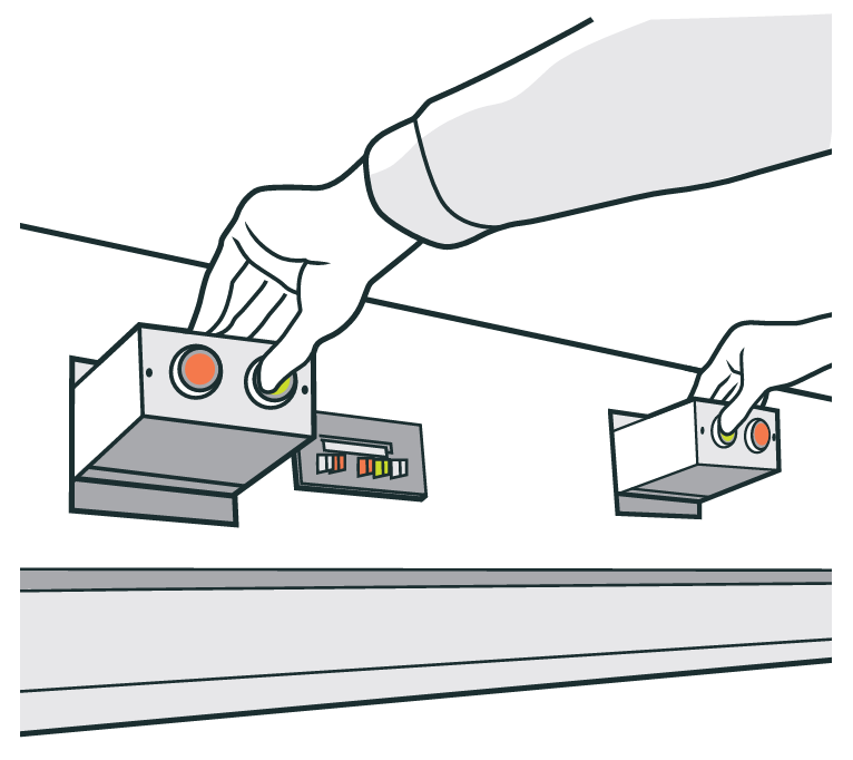
Two-hand operation is where two operation buttons need to be pushed at the same time, and held, to allow a machine to operate.
This makes sure that the operation of the hazardous operation cannot happen until both hands are clear of the danger area.
Only use this method to isolate people from machinery hazards as a last resort. Two-hand controls only protect the machine operator, not other people who may be near.
Two-hand controls should:
- need to be turned on together (so people cannot tape one control down)
- need to be held to run, so the machine stops immediately when the control is released
- be spaced well apart and shrouded so one arm cannot run both controls.
The rear and sides of the machine should be guarded by fixed guards to prevent access by other people.
Two-hand controls should meet the standard of AS/NZS 4024.2601 = Two-hand controls devices – principles for design and selection.
Pressure-sensitive mats
Pressure-sensitive mats are designed to cut the machine's power if someone steps on them to access a dangerous part.
Only use pressure-sensitive mats when you cannot use physical barriers or other methods of isolating people from hazards.
Pressure-sensitive mats use well-spaced electrical or fluid switches or valves in a mat. The mat covers any entries to a restricted space. Pressure on the mat stops the automatic operation of the machine. You should design the guard so no one can step over or around it into a restricted area.
Operate and maintain pressure-sensing safeguard systems to the manufacturers' instructions. Keep records of any maintenance, inspection, commissioning and alteration to a presence-sensing system, as well as any test results. Make sure workers and health and safety representatives can access the records.
Because pressure-sensitive mats do not usually show any visible sign of failure, use a control system that shuts down the machine if a mat fails.
Locked guards and gates
Locking guards and gates need a responsible person (usually a manager) to hold the key at all times.
This person needs to also make sure the gate is not opened until the machine is switched off, isolated and has stopped.
Only use locked guards and gates if there are no practical alternatives.
Senior management in association with staff should write, approve and monitor any safe operating procedures and monitor the effectiveness of the safety process as a temporary means to minimise the hazards.
Isolation, hold cards and lock-out devices can also be used so a machine is not accidentally restarted.
Adjustable guards
Adjustable guards are made up of a fixed guard with adjustable elements that are moved to suit each task. They can be:
- self-adjusting – guards that are forced open by the entry of work
- distance guards – barriers that can be moved to a safe distance from the danger zone.
Guards that move out of the way for each operation (automatic guards) need special care. Hazards can be created between the guard and:
- machine
- person
- work piece.
Staff need full training on using and adjusting these guards. These guards are only effective when people use them correctly.
Emergency stop devices
When emergency stop devices are installed, they are only ever a back-up for other control measures.
Emergency stops should NOT be used to lock-out the machine. Because the actuators can separate from the contacts, the control can show the machine is off when it is actually on.
Do a hazard assessment when choosing an emergency stop device and consider:
- whether part of the machine still needs to work in an emergency situation
- what other safety features still need to work (such as pressure release valves)
- whether the stop introduces any new hazards
- what level of integrity any associated circuitry needs.
Make sure emergency stop devices:
- are prominent, and clearly and durably marked
- are immediately accessible to each user of the machine
- have red handles, bars or push buttons (labelling can also be used) on a yellow background
- are not affected by electrical or electronic circuit failure.
Other considerations include:
- whether stop devices should be easily seen in contrast to their surroundings
- the best access for workers – for example near where someone can be trapped in the machine
- the environment the machine is used in (for example whether the device is exposed to dust, chemicals, temperature extremes or vibration)
- the number of emergency stop devices needed (if the machine is large, several devices or pull wires may be needed)
- a manual way to reset an emergency stop device
- a regular testing routine to check the device still works.
Badly placed emergency stop devices may slow shutdown in an emergency and encourage dangerous practices, such as:
- reaching across moving parts
- failing to shut down machinery when there is a problem
- allowing one worker to start the machine while another is in a dangerous location (such as cleaning a machine).
When there is more than one device, use a safe procedure so machinery cannot restart during maintenance or other temporary situations (such as a blockage of product). A lock-out and tag-out system is essential to isolate the machine from a power source to stop accidental start-up (see Section 9 Lockouts and Isolation procedures)
Colour coding
It is good practice to paint safety guard posts or frames yellow and any mesh black so it can be seen through more easily and staff do not need to open the guards for observation as much.
It is good practice to:
- use high visibility yellow paint for the guard that is different from the machine's colour
- paint surfaces behind the guard a bright or contrasting colour (like blue or red).
This will make it easier for workers to see if a guard is out-of-place.
8.2 Other control measures
There are other control measures that minimise the risk of harm that can be used alongside machine guarding.
Developing work procedures
Work procedures are needed to make sure that hazard control measures are effective. Work procedures should:
- define responsibilities for management, supervisors and workers
- have systems to make sure appropriate guarding is procured and correctly installed
- explain how workers will be trained and supervised to make sure the machinery is only used with the guarding in place
- require workers to follow the work procedures
- have arrangements to maintain the machine and guards
- have a system for workers to report malfunctions or problems with machinery
- have emergency procedures and training for staff on what to do.
Providing information on machinery
PCBUs have a duty to provide workers with training on the machinery being used.
The employer or person in control of the workplace should not let anyone use a machine unless they have had training on:
- the actual and potential hazards of the machine
- all the precautions to be taken.
This includes making sure that there is documented information for the user on the particular machine. This information could include:
- the machine's intended use
- a description of the machine's controls (especially emergency stops)
- operating instructions, including start-up preparations, process change-over and shutting down
- common faults and any reset instructions the user may need
- any guards or protective safety devices for particular hazards
- safety sign descriptions and details
- any prohibited uses or likely misuse
- any hazards the manufacturer could not eliminate
- any personal protective equipment that needs to be used
- any training that is needed.
This documentation could be in printed or electronic form but it should be readily available and easily accessible. It should also be in a form that workers of different languages and literacy levels can easily understand.
Maintenance
Work procedures should identify any maintenance needed to keep control measures effective. Looking at maintenance of control measures is an important part of the implementation process.
So maintenance can be done safely, consider:
- the ease of accessing parts
- ensuring machinery parts are safe to maintain
- ease of handling
- designing machinery to reduce the range of tools and equipment needed for maintenance.
Talking with your workers
Involving your workers (and their health and safety representatives) in managing risks around the use of machinery is essential. It is also good practice.
Your workers will likely know more about the hazards of their work than you do. These are tasks that they do every day. They know what can go wrong and they know the shortcuts – the actions and processes that make the job simpler or faster but which can often create risk.
Involve them when:
- new machinery is introduced
- changes are made to existing machinery
- changes are made to how they work.
They can help develop measures to eliminate or minimise hazards before any incident or injury occurs.
Training and information
Employers must make sure, so far as is reasonably practicable, that all workers receive training appropriate to their work. The workers should:
- have adequate knowledge and experience so that they are not likely to cause harm to themselves or other people
- be adequately trained in the safe use of plant and machinery
- be adequately supervised by someone with knowledge and experience if they themselves are still gaining knowledge and experience.
Personal protective equipment (PPE)
Workers may need PPE when working with machinery particularly machines that make heat, fumes, noise or other hazards.
PPE should be provided by the employer. If PPE is to be used it must be fit for purpose and:
- suitable for the nature of the work and any hazards associated with the work
- a suitable size and fit and be reasonably comfortable
- be compatible with any other PPE the worker is required to wear.
Workers must have training in how to wear and use their PPE.
When assessing PPE needs, talk with your workers about what new risks the PPE may create, and how you can eliminate them or minimise them. For example, some types of hearing protection can affect workers' situational awareness such as preventing them hearing approaching mobile plant.
8.3 Safe systems of work
A safe system of work is a formal work procedure developed after a systematic examination of a task to identify all the hazards. It is an administrative control.
It defines safe ways to work so hazards and risks are minimised. When hazards cannot be eliminated or isolated, you may need to use a safe system of work.
A safe system of work should never be used as the main hazard control without first assessing whether the hazards can be eliminated, or isolated with guarding, either provided by the manufacturer or retrofitted to existing machinery.
Workers need extra training, more supervision and other protective measures when using a safe system of work. These also need to be documented.
8.4 Reviewing effectiveness of control measures
Once control measures are in place, they should be regularly monitored and reviewed. To do this, it is useful to ask the following questions:
- Have control measures been implemented as planned?
- If control measures have not been implemented, why not, and what is happening in the meantime?
- Are the control measures being used correctly?
- Are the control measures working?
- Have the control measures isolated or minimised the risk from the hazard as intended?
- Have the control measures made any new hazards?
- Have the control measures made any existing hazards worse?
To answer these questions, you should:
- talk with workers, supervisors and any health and safety representatives
- measure levels of exposure (for example, take noise measurements where a noise source was identified)
- refer to manufacturers' instructions
- monitor incident reports
- contact industry associations, unions, government bodies or health and safety consultants.
When deciding when to monitor and review control measures, consider:
- the level of risk – high risk hazards need more frequent assessments
- the type of work practices or machinery involved
- whether new methods, tasks, equipment, hazards, operations, procedures, rosters or schedules have been introduced
- whether the environment has changed
- any indication that risks are not being controlled.
9.0 Lockouts and isolation procedures
This section looks at how to use lockouts to safely isolate and de-energise the parts of machinery that could harm workers when servicing, maintaining or cleaning the machinery.
9.1 Lockout systems and isolation procedures
Lockout systems are used to safely isolate machinery from its power source. They are used when someone needs to inspect, repair, maintain, alter or clean the machine, or when it is to be withdrawn for assessment or repair.
The method used to isolate depends on the type of machinery.
Employers should develop these safe operating procedures with employees. Once a procedure has been put in place it should be strictly obeyed.
Employers need to make sure there is a safe system to isolate all machinery from power sources.
They must:
- have procedures to prepare a machine for the application of isolation devices, locks and tags
- train and instruct workers in the system so they are competent to isolate or lock-out and tag-out machinery
- give supervision to make sure that isolation procedures are followed.
Workers trained in the safe system of isolation for machinery need to make sure the system is followed at all times.
If the machine is powered by electricity, the employer or supervisor should have a qualified electrician remove the equipment from the source of electricity. Where other sources of power are used, the parts that are removed to achieve isolation should also be kept in a place where they cannot be accessed by other workers.
If access to machinery is required and it is not practical to stop it, the employer, principal or duty holders needs to ensure that a competent person is present.
9.2 A competent person is key to planned isolation
Only people competent in the work systems and processes of the business, and the operation of the machinery should make decisions about the isolation of the machinery.
The competent person is the key person to:
- stop and isolate the machine
- minimise any risks associated with identified hazards (including telling any workers who may be affected by isolating the machine).
The competent person needs to make sure:
- all energy sources are de-energised and isolated using an isolation device, and locked out using a lock-out device
- all energy-isolating devices are activated and all switches and valves are in the off or safe position, to stop any attempts to activate the machine
- stored energy is released or restrained, including, for example, completing the cycle of a flywheel, releasing steam and bleeding valves
- an out-of-service tag is fixed to the machine and danger tags are fixed to the energy sources and operating controls
- tests are in place to de-energise and isolate all energy sources, to make sure the machine cannot be re-energised/ re-started
- the machinery is isolated before any inspection, repair, maintenance, alterations, cleaning or withdrawal happens.
The competent person who isolated the machinery needs to be the one to remove the lock-out equipment and make the machine operational again.
A procedure should be in place where this is not possible (such as where work is done over a number of shifts or the worker has gone home sick).
If the competent person cannot complete all steps in a planned isolation, they need to make sure a competent person develops written procedures and that these are followed by the person doing the work.
9.3 Isolation, hold cards and lockout devices
Chains, clasps and locks are examples of devices that can be used to isolate machinery. Isolation devices should be reliable and clear.
Each lock should:
- be strong enough to take physical abuse, either intentional or unintentional
- be made of material suitable for the environment
- have only one key and one owner who is responsible for it.
Master or spare keys should be kept in a designated place, away from the workplace and under the control of a competent person.
There needs to be strict procedures about when to use spare keys. They need to only be used in an emergency after thorough safety checks are done.
Lock-out and tag-out cards should be used together and be attached to the power controls of isolated machinery. This reduces the chance of someone starting the machinery inadvertently.
Lockout and tagout cards need to clearly state that under no circumstances should the machinery be connected to the power source until the hold card is removed by the person named on the tagout card.
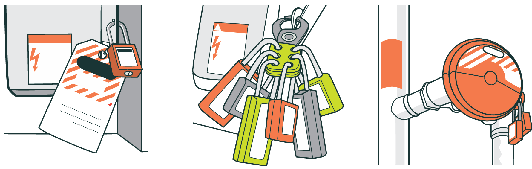
Include information on the tag-out card of the actual or potential danger.
Lock-out devices make sure people are out of the danger area before a machine can be started. They are mechanical-locking mechanisms used to physically lock machinery controls so they cannot be used.
Use lock-out devices when people have to work on or inside machinery and are out of sight of other people in the workplace.
Anyone who has to work in a hazardous area should have a lock-out device that identifies who is protected by the device. The lock used with these devices should be durable and must only have one key, held by the operator.
Tag-out cards are sometimes referred to as danger tags, restricted-use tags and warning tags. Use a tag out card with lock-out devices and isolation to improve worker safety.
For more information, see Keeping workers safe when servicing machinery [PDF, 96 KB]
10.0 Choosing the right guard
Choosing the right guard for the machine will create a physical barrier between a worker and the dangerous parts of the machinery.
When choosing guards, careful attention to design and layout, and the use of the machine, can remove many health and safety hazards and can prevent health issues and injuries occurring.
Note: Figure 9 does not take other protective devices, such as two-hand controls, into account
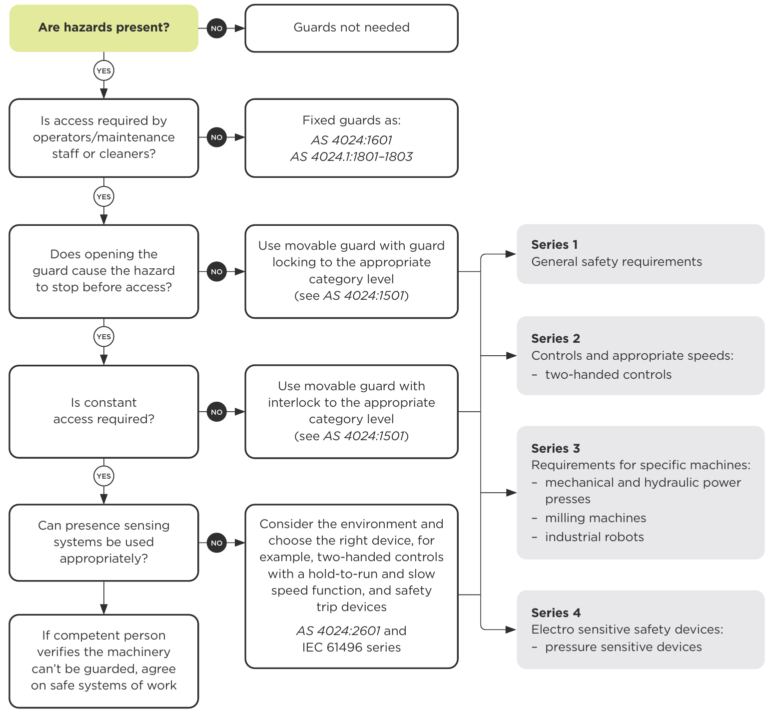
- Are hazards present?
- No: Guards not needed.
- Yes: continue.
- Is access required by operators/maintenance staff or cleaners?
- No: Use fixed guards as: AS 4024:1601 and AS 4024.1:1801–1803
- Yes: continue.
- Does opening the guard cause the hazard to stop before access?
- No: Use a movable guard with guard locking to the appropriate category level (see AS 4024:1501)
- Yes: continue.
- Is constant access required?
- No: Use a movable guard with interlock to the appropriate category level (see AS 4024:1501)
- Yes: continue.
- Can presence sensing systems be used appropriately?
- No: Consider the environment and choose the right device, for example, two-handed controls with a hold-to-run and slow speed function, and safety trip devices AS 4024:2601 and IEC 61496 series.
- Yes: If a competent person verifies the machinery can't be guarded, agree on safe systems of work
For the last three 'No' answers, AS/NZS 4024 Safety of machinery series 1 to 4 are also highlighted.
End of text alternative.
10.1 Choosing a guard
Machine guarding options in order of preference:
- where access is not needed during normal operation, maintenance or cleaning, use a permanently attached physical barrier
- where access is needed during normal operation, maintenance or cleaning, use an interlocked physical barrier
- where opening the guard stops the hazard before access, use a moveable guard with guard locking interlock, and safety switches of an appropriate category level.
If constant access is needed:
- use a safety interlock system that meets the appropriate rating in its failsafe control category (a hazard and risk assessment determines what failsafe category is needed)
- add extra protections to minimise hazards, such as safety trip devices, accessible emergency stops, slow speed and/or two-hand hold-to-run control devices.
If there is no practicable way to guard a hazard, a safe system of work needs to be put in place. For more information on Safe systems of work see section 8.3
10.2 Basic rules for guard design
The basic rules for guard design are:
- use materials of suitable strength and good quality
- use the right guard. Custom-designed is best – poorly designed or inappropriate guards can cause injuries
- the environment and the needs of operators and maintenance workers affect how well a guard works.
If a guard is used from another machine, check carefully that it:
- fits the target machine
- is strong enough for the new use
- controls the risk
- is not faulty.
When selecting or designing a guard, think about how it might be misused or how workers may set out to defeat it. It is human nature to try and find an easier or quicker way of doing something. This applies very much with operators, machinery and guarding.
Talk with your operators and workers. They are the ones who will tell you about how they actually do the task (rather than how you think they should do the task) and the short-cuts they will look for.
Design your guarding so there is less possibility (or less incentive) to try and defeat it.
10.3 Guarding of operational and non-operational parts
When deciding what needs to be guarded, look at operational and non-operational parts of the machine. Start with obvious operational parts such as:
- rollers – mills
- saws – circular and band saws
- drills and drill chucks
- cutters in metal working machines, including the blades of guillotines and the tools of power presses
- rotary beaters, such as in food mixers
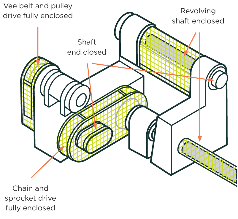
Then consider non-operational parts such as:
- chains and sprockets
- belts and pulleys
- gears (including rack and pinion sets)
- shafts (plain or threaded)
- flywheels.
10.4 Choosing the material for guards
There are four main considerations when choosing material to make a guard:
- strength and durability – use of non-metallic materials in corrosive environments
- effects on machine reliability – a solid guard may cause the machine to overheat
- visibility – there may be operational and safety reasons for needing a clear view of the danger area
- control of other hazards – for example the use of a material that will not eject molten metal.
10.5 Servicing and maintenance considerations
When designing guards, consider what safe procedures are needed for their removal for repair, clearing jams and breakdowns.
Servicing matters to consider include:
- following documented safe work procedures, including manufacturers' instructions
- proximity to hot or sharp parts
- cool-down or warm-up periods
- run down periods
- lock-out provisions or permission for guard removal
- enough room to do tasks without risk of injury or strain
- stored energy in the machine or materials being processed
- any additional hazards from maintenance procedures – such as testing while the machine is unguarded (a 'dry run' or 'trial run'), working at heights, use of solvents
- maintaining or updating service records. Maintenance considerations include:
- where servicing is needed
- how much servicing is needed
- what kind of servicing is needed
- how often servicing needs to be done.
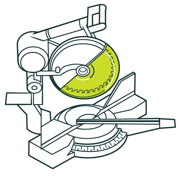
10.6 Guards for exposed rotating cutting machinery
Exposed rotating cutting machinery includes:
- cut-off saws
- milling machines
- friction cutting machinery
- boring machinery.
Hazards arise from the exposed blades and risks include cutting people or entanglement.
Guards (or visors) that move must stay close to the work piece. The cutter's teeth can be exposed if the visor is:
- not attached to the fixed guard
- in a poor position
- jams in the open position.
10.7 Pulleys and drives
Pulleys and drives are used in many machines. Nip-points are the main hazard. They need to be guarded so no one can get entangled.
Interlocked guards are preferable for pulleys and drives. In some cases, a hinged section may be appropriate to access the machine when setting it. The guard should be designed and installed so that a tool is needed to remove and replace it.
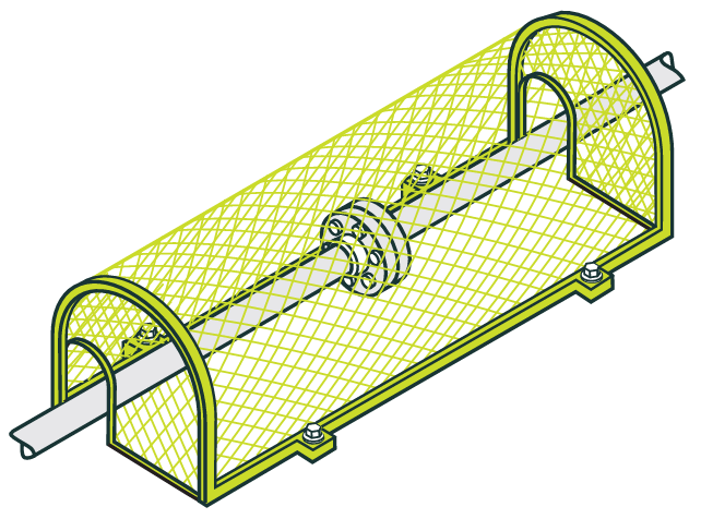
10.8 Rotating shafts and rollers
Interlocked guards are preferable for rotating shafts and rollers, such as:
- couplings
- spindles
- fan-shafts
- ironing rollers.
Guards should stop loose clothing and long hair getting caught in rotating shafts. Even with a guard, operators should be warned not to wear loose clothing (such as long-sleeved shirts or jackets) and tie long hair back or wear a head covering.
10.9 Conveyors (bulk handling)
Conveyors move materials from one place to another. Types of conveyors include belt, auger, roller, and bucket conveyors.
Hazards
The main hazards of a conveyor are the many in-running nip-points, which can entangle, crush and abrade people. The drive system can also pose risks of entanglement or abrasion.
Control measures
Fixed guards that enclose in-running nip-points and the drive mechanism are usually the best way to guard conveyors.
Large conveyors, such as stockpilers, generally need both carry idlers and return idlers guarded where they are under high tension and accessible. This should be done to an appropriate standard, such as AS/NZS4024.3611 Conveyors – belt conveyors for bulk material handling requirements or equivalent.
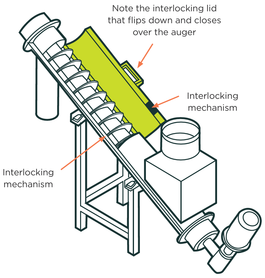
Electrical isolation (lock-out and tag-out)
See Section 9 for more details on lock-out, tag-out. See also Keeping workers safe when servicing machinery [PDF, 96 KB]
Emergency stop controls
A lanyard-type pull-wire emergency stop is the best emergency stop for exposed belt conveyors where workers have to access the belt area while the conveyor is in use (such as when placing and removing parcels at a transport depot).
The lanyard type means wherever someone is working on the conveyor, they can reach the emergency stop. Emergency stop controls should be manually reset before the conveyor can be restarted from its normal start control.
Access provisions
The machine design should let people do routine adjustment and lubricate and maintain the machine without removing guards or taking much dismantling.
Wherever practical, people should be able to lubricate and maintain the machine from outside the danger area. If people need access to the danger area (such as for machine setting), make sure to use safe isolation procedures.
Training
Make sure people working around conveyors are trained on how to use the machinery and are aware of the potential hazards.
For more information on minimum safety requirements for the design, installation and guarding of conveyors and conveyor systems and training see:
- AS/NZS 4024.3611: Conveyors – belt conveyors for bulk materials
- AS/NZS 4024.3612: Conveyors – chain conveyors and unit handling conveyors
- AS/NZS 4024.3614: Conveyors – mobile and transportable conveyors.
10.10 Press brakes
A press brake is a variable stroke machine generally used for straight bending and forming of material, such as sheet metal and heavy gauge material.
Hazards
For press brakes, the main hazards are:
- the die sets mounted to the main moving beam and table coming together to form the product
- the work piece and the press frame coming together in the fold-forming process.
The impact from both can have a pinching, crushing, cutting or shearing motion, which creates a risk to the operator of being crushed or cut.
Drive belts on press brakes have in-running nip points, which present a risk of entanglement and abrasion. Hydraulic hoses may leak or burst, causing slip hazards and workers getting sprayed with hydraulic fluids under pressure.
Control measures
The front dies of a press brake and its sides and rear require guarding. Three forms of guarding for the front of the dies on a press brake are:
- a fixed guard
- interlocked guard
- a light or presence-sensing system.
Where workers have to hold or stabilise the material, or need frequent access to closing dies, presence-sensing devices may be required to ensure safe operation. Presence-sensing devices may be light curtains or light beams. Automatic stops should also be guarded and back-gauging equipment is recommended.
Presence-sensing devices (cameras, light curtains or light beams) may not protect the operator in all circumstances.
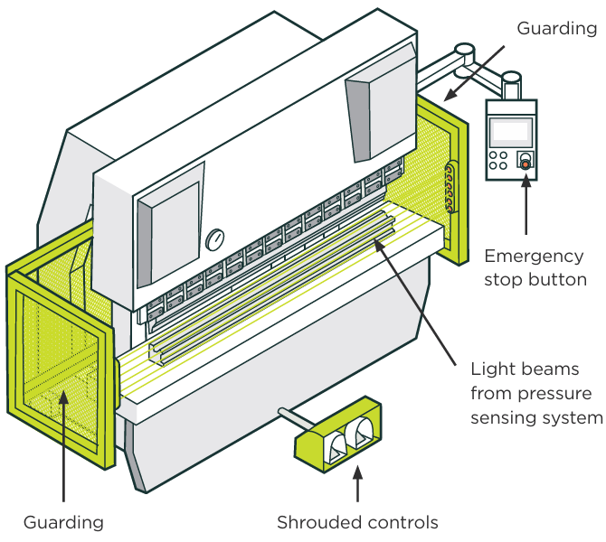
Safe system of work for press brakes
On occasions it may not be possible to perform work with the guarding system in place. Removal of or turning off a guard should only occur if the guard makes it impracticable to perform close work or jobbing and a hazard and risk assessment is carried out by a competent person. A safe system of work should be developed in conjunction with the employer and operators and approved by a competent person with appropriate knowledge and experience of machine safety.
In cases where guarding of any moving parts of the plant does not eliminate risks of entanglement, or where it is not practicable to guard the parts, people should not be able to operate or pass close to the moving part unless a safe system of work is in place to reduce the risks.
Additional training, experience and higher levels of supervision, and other protective measures may be required and will need to be documented.
For more information on safe systems of work see section 8.3 in this guideline.
Closed tool method
The closed tool method reduces the press brake's opening to 6 mm which limits the risk of introducing a part of the body into this hazardous zone. The 6 mm is measured from distance between the point of the upper tool and the top of the bottom die.
Where possible, the closed tool method should be used with a safety light curtain, a laser beam device or a two-hand control device.
10.11 Robotics
Using robots can remove the more traditional hazards of working with machinery. They can do high-risk work, for example in the biotechnology field.
It is wrong to think that robotic operations are safe just because there is little or no worker interaction. Hazards when using robotics can come from:
- errors during use
- ejection of materials
- trapping points
- failures and malfunctions.
Hazards can also come up during installation, repair and maintenance. There may also be biological, chemical or environmental hazards.
A hazard assessment should be done to ensure workers' safety during all phases of the machinery's life and use. Follow a hazard management process (with reference to the manufacturer's instructions) during installation or commissioning, testing, start-up, repair and maintenance.
Hazards and risks
Robots have inherent dangers. Some of the hazards of industrial robot use include:
- Impact. Robots can move at high speed in an unexpected direction either in a straight line or circular directions. The robot can also eject work pieces, off-cuts or molten metal. Workers are at risk from being hit by the robot or parts of the work.
- Trapping points. These can be made by the robot's movement or other machinery – such as work carriages, pallets or transfer mechanisms. With the robot itself, trapping points are found on the arm of the robot, between the arm and the column, and between the arm and fixed objects. Workers can be crushed by or entangled with the robot, including being crushed between a rapidly rotating robot arm and barriers close by.
- Control errors. These come from faults in the control system of the robot (such as software, electrical interference, programme corruption and sub-controls associated with the electrics, hydraulics and pneumatics).
- Human error. These can happen during programming, teaching, maintenance and repair, working close to the robot or at loading or unloading stations.
- Failure or malfunction. Electrics, hydraulics and pneumatics can all create hazards when they fail.
- Biological or chemical hazards. These can happen when robots are used to reduce the risks from hazardous or infectious processes. Workers may risk inhaling or absorbing hazardous substances. In this case, the work process needs close attention, along with any breakdown or emergency procedures that may be needed – such as for spillage, contamination or breach of the system.
- Environmental hazards. These include dust vapours, fumes, lasers, noise, radiation and flammable and explosive atmospheres that can cause serious harm, such as burns and inhaling or absorbing hazardous substances and hearing loss.
Control measures
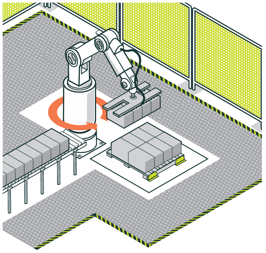
Industrial robots can be made safe using one or more guarding and presence-sensing devices. Control measures include:
- enclosing the robot
- restricting access
- turning the robot off when people are near.
There are three levels around a robot workstation with different hazards and precautions to be considered.
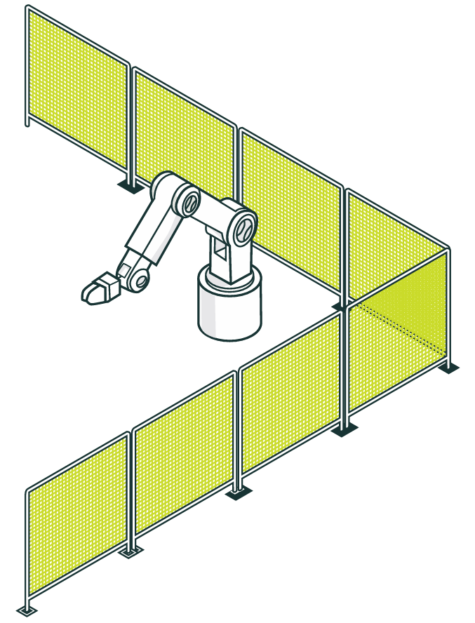
- Level 1 is the workstation perimeter, usually a physical barrier guarded with an interlock gate and possibly with presence-sensing devices.
- Level 2 is within the workstation (where the robot moves). Here safety systems should detect if someone is present, usually with presence-sensing devices.
- Level 3 is contact with the robot. A safety system should detect a person touching the robot and stop it moving immediately using safety trip devices or sensors.
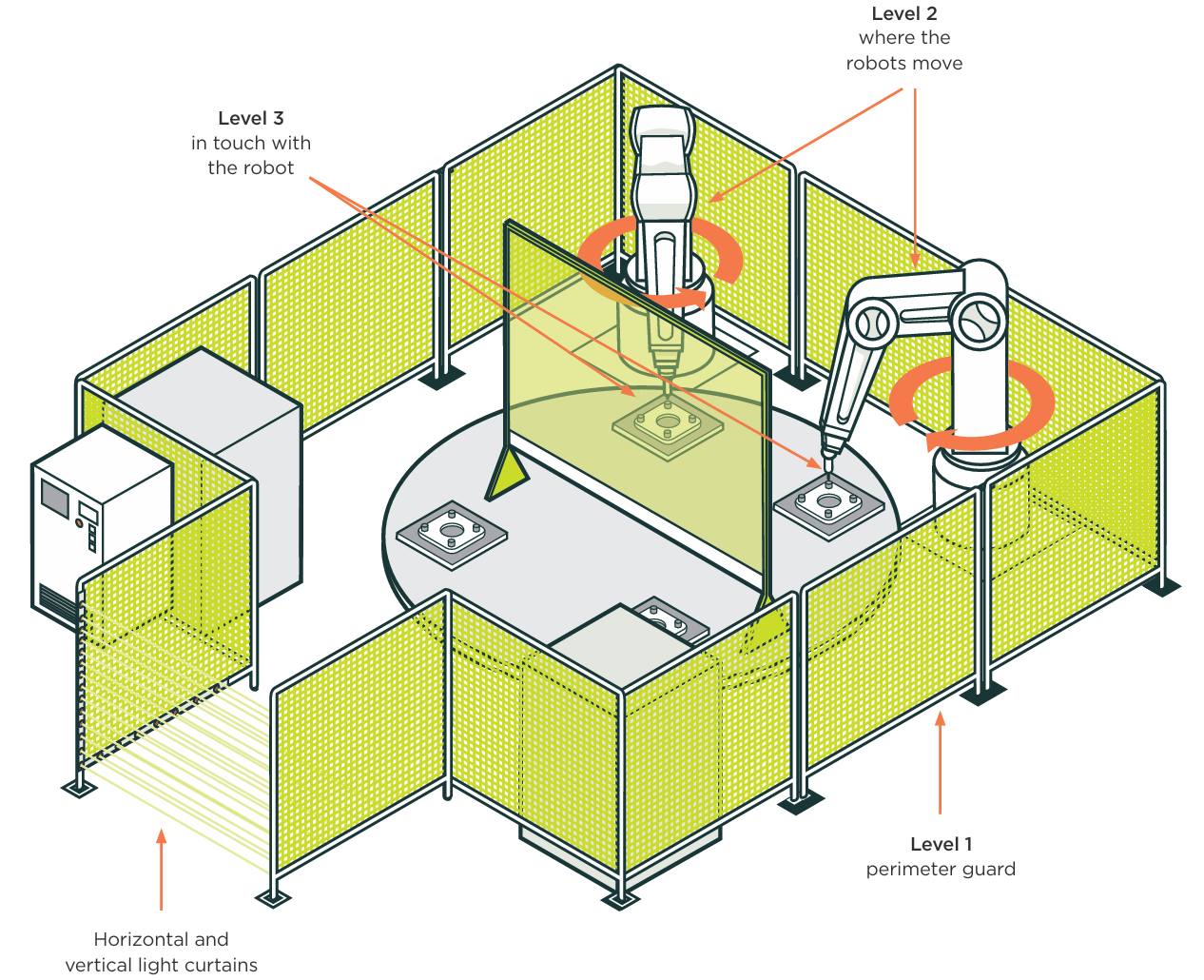
Fixed or distance guards at (Level 1) are practical as long as the guard does not interfere with the mechanism of the robot. Someone should have to use tools to remove the guards to enter the restricted danger area. Guards or fences should be placed so people cannot reach into a restricted area.
Any openings for feeding material in should be designed to keep every part of a person away from any hazard.
To stop trapping, any fixed barriers should be at least 500 mm from the robot work envelope (extreme reach of the robot arm and tooling).
Design and place presence-sensing devices (such as photoelectric curtains) to detect if anyone enters a restricted space or danger area (Level 2). The device should stop the automatic operation of the robot when entry is detected. Operation must also stop if this device fails.
You can use laser scanners or pressure-sensitive mats as a back-up safety protection for high-risk machinery in areas inside the primary light curtain. This way the system cannot restart while someone is inside the area protected by a light curtain.
Additional control measures
Because robots are highly technical and programmable, consider extra safeguards beyond just guarding moving parts. These include making sure:
- only competent people can access and start the robot system
- no one can access the robot through or by removing associated machinery, such as conveyors, transfer systems, loading stations or trolleys.
If people have to enter the robot cell (Level 2) while the robot is working, the control system should make sure the robot runs with reduced force. The robot also needs a sensor to stop it immediately if it hits someone.
Safe operating procedures can also minimise some of the risks of working with robotics. A safe work system should have procedures for entry, including who can access the robot to do identified tasks, maintenance and repair. Inspecting and maintaining a robot can present different hazards from working with the robot. Assess all hazards for risks.
Staff must be trained to control the hazards of working with industrial robot machines. Inadequate training can increase risks at most stages of robot operation.
Control systems
Robots usually have programmable electronic start and control systems. These control systems should be protected from unauthorised access, such as by putting them in a lockable cabinet or room. Make and place controls so people cannot accidentally start the robot. This can be done a number of ways, including shrouding, guarding, gating or appropriate positioning.
If people can access the robot, it needs to be isolated from its power source.
For more information see:
- AS/NZS 62061:2025 Safety of machinery – Functional safety of safety-related control systems
- AS/NZS 4024.3301 Safety of machinery – Robots for industrial environments – Safety requirements
- AS/NZS 4024.3302 – Robots and robotic devices – Safety requirements for industrial robots
- AS/NZS 4024.3303 Robots and robotic devices – Collaborative robots.
Master switches
Robots should have master switches to cut power to any moving part of the robot.
11.0 Buying second-hand or importing from overseas
If you buy second-hand machinery or import machinery directly you still have duties.
PCBUs importing machinery from overseas have duties under HSWA. These include making sure the products they import do not create health and safety risks for the people that use them and those nearby, so far as is reasonably practicable, and to make sure the products they import have been tested so they are safe for use in a workplace
PCBUs importing machinery from overseas have specific duties under HSWA (See Appendix 3). These include, so far as is reasonably practicable, making sure the imported products do not create hazards for:
- people that use them
- people nearby, and
- the products they import have been tested so they are safe for use in the workplace including carrying out any calculation, analysis or ensuring that it has been carried out
A PCBU importing direct from overseas will have the same duties and responsibilities as an importer.
11.1 Buying second-hand machinery
The duties of suppliers do not apply to the sale of second-hand plant, and second-hand plant that is sold 'as is'. PCBUs purchasing second-hand machinery still have a duty to make sure that the plant or machinery does not create risks for their workers.
If you are a PCBU buying second-hand plant or machinery, you should:
- make sure it is suitable for what you want it to do (for example, is it powerful enough?)
- check as much as possible the history and previous use of the machine. Make sure it is not at the end of its life.
- get as much information as possible on the specifications, use, characteristics and maintenance of the machine. This might be from the seller or from the manufacturer.
- think about where you are going to be using it. Is there sufficient space or could the position cause risks for the operator or other workers?
- look closely at any guarding the machine currently has. Is it built to a suitable standard? Will it work in your operation?
- consider having it checked by a certified engineer
11.2 Buying machinery from overseas with CE marking
Under HSWA, PCBUs have a duty to ensure, so far as is reasonably practicable, that machinery or plant is safe.
The benchmark for machinery safety in New Zealand is that the machinery meets AS/NZS 4024 standards.
A CE marking is a mandatory mark for certain products sold on the European market. It indicates compliance with the European Union Directives.
A machine built in Europe will generally be built to CE certification and would generally meet New Zealand standards. A machine built outside of Europe that uses the CE certification may not be built to those standards.
So, a machine with CE mark does not mean that it automatically meets New Zealand's specific legal requirements under HSWA.
To be certain that an imported machine meets AS/NZS 4024 standards, it is recommended that it is checked by a suitable competent person, such as a Chartered Professional Engineer (CPEng), a Certified Machinery Safety Expert or a recognised accredited laboratory.
Appendices
Appendix 1: Glossary
AS/NZS – Australian/New Zealand Standard
A reference to an Australian/New Zealand Standard, described by numerals and a title.
Business or undertaking (see also PCBU)
The usual meanings are:
- business: an activity usually carried out with the intention of making a profit or gain
- undertaking: an activity that is non-commercial in nature (for example, certain activities of a local authority or a not-for-profit group).
CPEng
A Chartered Professional Engineer (often written as CPEng) is an experienced engineer who has been assessed as meeting a quality mark of competence.
Competent person
Someone who can consistently demonstrate the skill and knowledge derived from experience and/or training for the type of work the person is tasked to do.
Control measure
A way of eliminating or minimising risks to health and safety.
Duty
A legal obligation to act responsibly according to the law.
Duty holder
A person who has a duty under HSWA. There are four types of duty holders – PCBUs, officers, workers and other persons at workplaces.
Eliminate
To remove the sources of harm (for example, equipment, substances or work processes).
Exposure monitoring
Measures and evaluates what your workers are being exposed to while they are at work. This can be:
- personal exposure monitoring (workers wearing a device while they work) or
- biological exposure monitoring (where blood or urine samples are taken to test for a substance workers are working with).
Fatigue
A physiological state where someone is unable to mentally and physically function as they usually would. This is caused by four main factors:
- missing out on sleep
- being awake for too long
- working and sleeping in the wrong parts of the body clock cycle
- workload (mental and physical).
Hazard
Anything that can cause harm. Under HSWA, hazard is defined as "includes a person's behaviour where that behaviour has the potential to cause death, injury, or illness to a person (whether or not that behaviour results from physical or mental fatigue, drugs, alcohol, traumatic shock, or another temporary condition that affects a person's behaviour".
Hazardous substances
Any product or chemical that has properties that are explosive, flammable, oxidising, toxic, corrosive or toxic to the environment.
Health
A person's physical and psychological health.
Health and Safety at Work Act 2015 (HSWA)
The key work health and safety legislation in New Zealand. HSWA applies to all work and workplaces unless specifically excluded.
You can find the full text of the Act on the New Zealand Legislation website.
Health monitoring
Looks at whether a worker's health is being harmed because of what they are being exposed to while at work (for example, hearing tests).
Interlocked guarding
Interlock guarding occurs when the act of moving the guard (opening, sliding or removing) to allow access, stops the action of the hazardous mechanism.
ISO
The International Organisation for Standardisation – an organisation that develops and publishes international standards that ensure quality and safety in products and services.
Machinery
Machinery is a collective term for machines and their parts. A machine is considered to be any apparatus that has interrelated parts and is used to perform work; machines may include an engine, motor, or other appliance that provides mechanical energy derived from compressed air, the combustion of fuel, electricity, gas, gaseous products, steam, water, wind, or any other source; and includes:
- any plant by or to which the motion of any machinery is transmitted; and
- a lifting machine, a lifting vehicle, a machine whose motive power is wholly or partly generated by the human body, and a tractor.
Minimise
To take steps that protect the health and safety of people by reducing the likelihood of an event occurring, reducing the level of harm to people if it does occur, or both.
Must
Indicates a legal requirement that must be complied with.
Officer
A person who has the ability to significantly influence the management of a PCBU.
This includes, for example, company directors and chief executives. Officers must exercise due diligence to ensure the PCBU meets its health and safety obligations.
Operator
A worker who operates some form of machinery.
Overlapping duties
When a PCBU shares duties with other PCBUs in relation to the same matter. When two or more PCBUs' duties overlap, the PCBUs must consult, co-operate and co-ordinate with each other.
Other persons at the workplace
Includes workplace visitors and casual volunteers (who are not volunteer workers).
These people have their own health and safety duties to take reasonable care to keep themselves safe and to not harm others at a workplace.
PCBU
In most cases a PCBU will be a business entity, such as a company. However, an individual carrying out business as a sole trader or self-employed person is also a PCBU.
A PCBU does not include workers or officers of a PCBU, volunteer associations with no employees, or home occupiers that employ or engage a tradesperson to carry out residential work.
Plant
Includes:
- any machinery, vehicle, vessel, aircraft, equipment (including personal protective equipment), appliance, container, implement, or tool; and
- any component of any of those things, and
- anything fitted or connected to any of those things.
Personal protective equipment (PPE)
Anything used or worn by a person (including clothing) to minimise risks to the person's health and safety.
This may include – but is not limited to:
- respiratory protective equipment
- protective helmets
- protective eyewear
- protective boots
- protective gloves
- hearing protection
- high-vis clothing
- safety harness systems.
Presence sensing devices
Presence sensing devices detect a person, or a body part approaching the danger zone and stops the dangerous operation of the plant.
Examples of presence sensing devices include pressure sensing mats, light screens and configurable scanners.
Prime mover
Prime mover means an engine, motor, or other appliance that provides mechanical energy derived from steam water, wind, electricity, gas, gaseous products, or any other source. It includes any device which converts stored or potential energy into movement or mechanical energy.
Reasonably practicable
What is, or was, reasonably able to be done to ensure health and safety, taking into account and weighing up relevant matters including:
- the likelihood of the risk concerned occurring or workers being exposed to the hazard
- the degree of harm that might result
- what the person concerned knows, or ought reasonably to know, about:
- the hazard or risk
- ways of eliminating or minimising the risk.
- the availability and suitability of ways to eliminate or minimise the risk
- after assessing the extent of the risk and the available ways of eliminating or minimising the risk, the cost associated with available ways of eliminating or minimising the risk, including whether the cost is grossly disproportionate to the risk.
For more information, see Reasonably practicable
Risks
Arise from people being exposed to a hazard (a source of harm).
Safe by position
Safe by position means so positioned that any person cannot reach or gain access to the dangerous parts.
Safe operating procedures
Safe operating procedures are written instructions that detail the steps that will be performed during a given procedure; including information about hazards and how these hazards will be controlled.
Safe system of work
Safe system of work means a formal procedure which results from systematic examination of a task in order to identify all the hazards. It defines safe methods to ensure that hazards are eliminated or risks minimised.
Transmission machinery
A mechanism that transfers movement from the prime mover to the machine. It can be a shaft, wheel, drum, pulley, system of fast and loose pulleys, gearing, coupling, clutch, driving belt, chain, rope, band or other device.
Upstream PCBUs
PCBUs who design, manufacture, import or supply plant, substances or structures, or who install, construct or commission plant or structures.
'Design' includes the:
- design of part of the plant, substance, or structure, and
- redesign or modification of a design.
Worker
An individual who carries out work in any capacity for a PCBU. A worker may be an employee, a contractor or sub-contractor, an employee of a contractor or sub-contractor, an employee of a labour hire company, an outworker (including a homeworker), an apprentice or a trainee, a person gaining work experience or on a work trial, or a volunteer worker.
Workers can be at any level (for example, managers are workers too).
A PCBU is also a worker if the PCBU is an individual who carries out work in that business or undertaking.
Workplace
Any place where a worker goes or is likely to be while at work, or where work is being carried out or is customarily carried out.
Most duties under HSWA relate to the conduct of work. However, some duties are linked to workplaces.
Appendix 2: Duty holders and certain duties
| Who they are | Examples | What are their duties? | For more information |
|---|---|---|---|
| Person Conducting a Business or Undertaking (PCBU) | |||
|
A person conducting a business or undertaking (PCBU) may be an individual person or an organisation The following are not PCBUs:
|
|
A PCBU has many duties. Key duties are summarised below. Primary duty of care section 36 of HSWA(external link) A PCBU must ensure, so far as is reasonably practicable, the health and safety of workers, and that other persons are not put at risk by its work. Managing risks section 30 of HSWA(external link) Risks to health and safety arise from people being exposed to hazards (anything that can cause harm). A PCBU must manage work health and safety risks.
Overlapping duties: working with other PCBUs section 34 of HSWA(external link) A PCBU with overlapping duties must, so far as is reasonably practicable, consult, cooperate and coordinate activities with other PCBUs they share duties with. Involving workers: worker engagement, participation and representation Part 3 of HSWA(external link) A PCBU must, so far as is reasonably practicable, engage with their workers (or their workers' representatives) about health and safety matters that will directly affect the workers. A PCBU must have worker participation practices that give their workers reasonable opportunities to participate in improving health and safety on an ongoing basis. |
Introduction to the Health and Safety at Work Act 2015
Identifying, assessing and managing work risks [PDF, 404 KB] |
| Upstream PCBU | |||
| A PCBU in the supply chain |
|
Upstream PCBU sections 39–43 of HSWA(external link) An upstream PCBU must ensure, so far as is reasonably practicable, that the work they do or the things they provide to other workplaces do not create health and safety risks. |
Introduction to the Health and Safety at Work Act 2015 |
| Officer | |||
| A specified person or a person who exercises significant influence over the management of the business or undertaking section 18 of HSWA(external link) |
|
Officer section 44 of HSWA(external link) An officer must exercise due diligence that includes taking reasonable steps to ensure that the PCBU meets their health and safety duties. |
Introduction to the Health and Safety at Work Act 2015 |
| Worker | |||
| An individual who carries out work for a PCBU section 19 of HSWA(external link) |
|
Worker section 45 of HSWA(external link) A worker must take reasonable care of their own health and safety, and take reasonable care that they do not harm others at work. A worker must cooperate with reasonable policies and procedures the PCBU has in place that the worker has been told about. A worker must comply, as far as they are reasonably able, with any reasonable instruction given by the PCBU so the PCBU can meet their legal duties. |
Introduction to the Health and Safety at Work Act 2015 |
| Other person at the workplace | |||
| An individual present at a workplace (not a worker) |
|
Other person at the workplace section 46 of HSWA(external link) An 'other person' has a duty to take reasonable care of their own health and safety, and not adversely affect the health and safety of anyone else. They must comply with reasonable instructions relating to health and safety at the workplace. |
Introduction to the Health and Safety at Work Act 2015 |
Appendix 3: Upstream duties – who is responsible for what and when
sections 39-43 of HSWA(external link)
A PCBU in the supply chain (upstream) also has a duty to ensure, so far as is reasonably practicable, that the work they do or the things they provide to other workplaces do not create health and safety risks.
An upstream PCBU is a business that:
- designs plant, substances, or structures
- manufactures plant, substances, or structures
- imports plant, substances, or structures
- supplies plant, substances, or structures
- installs, constructs or commissions plant or structures.
Upstream businesses are in a strong position to eliminate or minimise risk. They can influence and sometimes eliminate health and safety risks through designing, manufacturing, importing or supplying products that are safe for the end user.
Example
A worker using a badly designed or poorly manufactured saw may be at risk of injury. This risk should have been eliminated or minimised, so far as was reasonably practicable, by the designer or manufacturer.
For more information, see Upstream duties
Upstream duties for designers
section 39 of HSWA(external link)
A designer creates or modifies a design for plant, substances or structures that are to be used or operated, or could be used or operated, in a workplace.
A designer has a duty, so far as is reasonably practicable:
- to make sure the products they design do not create health and safety risks for the people that use them and those nearby
- to make sure the products they design have been tested so they are safe for use in a workplace
- to give the following information to those who will use the designed products:
- the design's purpose or intended use
- the results of any calculations or tests
- any general and current relevant information about how to safely use, handle, store, construct, inspect, clean, maintain, repair, or otherwise work near the designed products.
These requirements apply across the product's entire lifecycle – from manufacture and construction, through to everyday use, decommissioning and disposal.
For more information, see Health and safety duties for businesses that design products for workplaces [PDF, 40 KB]
Upstream duties for manufacturers
section 40 of HSWA(external link)
A manufacturer makes plant, substances or structures that are to be used, or could be used or operated, in a workplace.
A manufacturer has a duty, so far as is reasonably practicable:
- to make sure the products they manufacture do not create health and safety risks for the people that use them and those nearby
- to make sure the products they manufacture have been tested so they are safe for use in a workplace
- to give the following information to those that will use the manufactured products:
- the purpose or intended use of each product
- the results of any calculations and tests
- any general and current relevant information about how to safely use, handle, store, construct, inspect, clean, maintain, repair, or otherwise work near the manufactured products.
These requirements apply across the product's entire lifecycle – from manufacture and construction, through to everyday use, decommissioning and disposal.
For more information, see Health and safety duties for businesses that manufacture products for workplaces
Upstream duties for importers
section 41 of HSWA(external link)
An importer imports plant, substances or structures that are to be used, or could be used or operated, in a workplace.
An importer is a business:
- that goods are imported by, or
- that goods are imported for.
Importation is another word for importing. Importation refers to the arrival of goods in New Zealand from a point outside New Zealand. These goods can arrive in any manner.
An importer has a duty, so far as is reasonably practicable:
- to make sure the products they import do not create health and safety risks for the people that use them and those nearby
- to make sure the products they import have been tested so they are safe for use in a workplace
- to give the following information to those who will use the imported products:
- the purpose or intended use of each product
- the results of any calculations and tests
- any general and current relevant information about how to safely use, handle, store, construct, inspect, clean, maintain, repair, or otherwise work near the imported products.
These requirements apply across the product's entire lifecycle – from construction or assembly, through to everyday use, decommissioning and disposal.
Imported products must also meet all New Zealand regulatory requirements relevant to that product.
For more information, see Health and safety duties for businesses that import products for workplaces [PDF, 41 KB]
Upstream duties for suppliers
section 42 of HSWA(external link)
A supplier supplies plant, structures or substances that may be used in a workplace.
A supplier has a duty, so far as is reasonably practicable:
- to make sure the products they supply do not create health and safety risks for the people that use them and those nearby
- to make sure the products they supply have been tested so they are safe for use in a workplace
- to give the following information to those who will use the supplied products:
- the purpose or intended use of each product
- the results of any calculations and tests
- any general and current relevant information about how to safely use, handle, store, construct, inspect, clean, maintain, repair, or otherwise work near the supplied products.
These duties do not extend to the sale of second-hand plant sold 'as is'.
These requirements apply across the product's entire lifecycle – from construction or assembly, through to everyday use, decommissioning and disposal.
For more information, see Health and safety duties for businesses that supply products for workplaces [PDF, 39 KB]
Upstream duties for installers, constructors or commissioners of plant or structures
section 43 of HSWA(external link)
An installer/constructor builds and/or assembles and installs plant and structures that may be used at a workplace. A commissioner performs adjustments, tests and inspections on plant and structures before they are used for the first time in a workplace.
An installer, constructor or commissioner has a duty, so far as is reasonably practicable, to make sure that the way the plant or structure is installed, constructed or commissioned does not create health and safety risks to the people that come into contact with it across the product's entire lifecycle – from construction or assembly, through to everyday use, decommissioning and disposal.
For more information, see An additional health and safety duty for businesses that install, construct or commission plant or structures for workplaces [PDF, 39 KB]
Appendix 4: Mechanical hazards in machinery
Prime movers
Prime movers are devices that turn energy into motion to power a machine such as:
- electric motors
- electric generators
- electric rotary converters
- water turbines
- the head and tail race of water wheels
- motors powered by internal combustion
Every moving part of a prime mover should be guarded
Every flywheel connected to a prime mover should be guarded
Transmission machinery
Transmission machinery can include gears, shafts, pulleys and belts, chains and sprockets or friction drives.
Every part of any transmission machinery should be securely fenced unless it is constructed or positioned so that it is safe.
All transmission machinery should have device in every room or workplace to cut the power to the machinery.
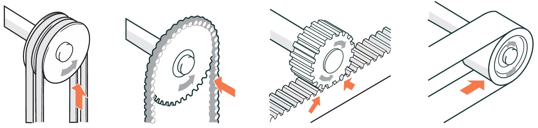
Drawing in or trapping hazards
Injuries can be caused when a part of a body is drawn into a 'nip point'. Below shows examples of drawing-in hazards.
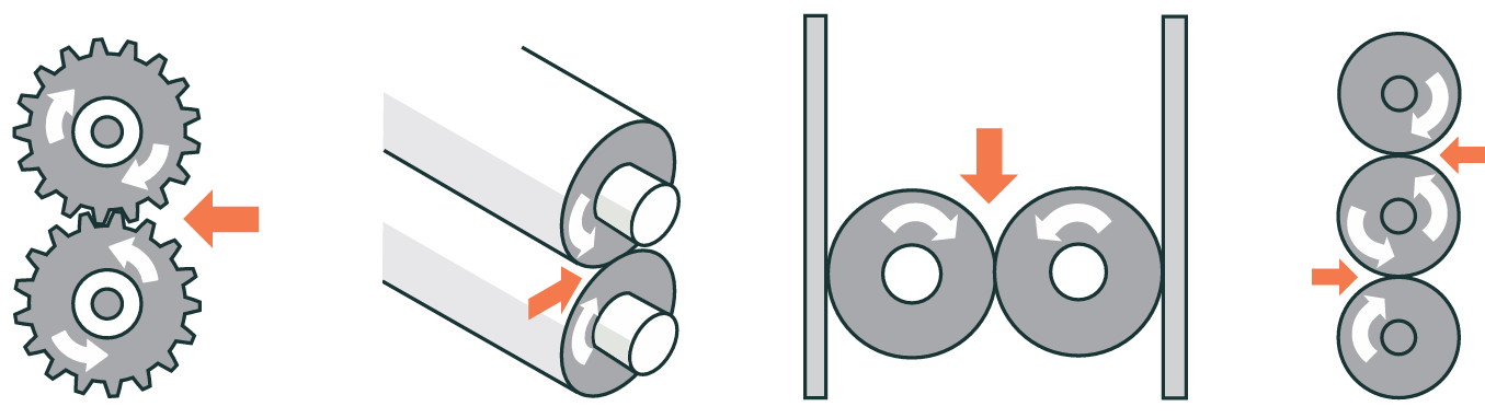
Crushing hazards
Crushing hazards happen when a person or part of their body is caught:
- between a fixed and moving part of a machine
- between two moving parts
- between a moving part and a fixed structure (such as a counterweight and the floor)
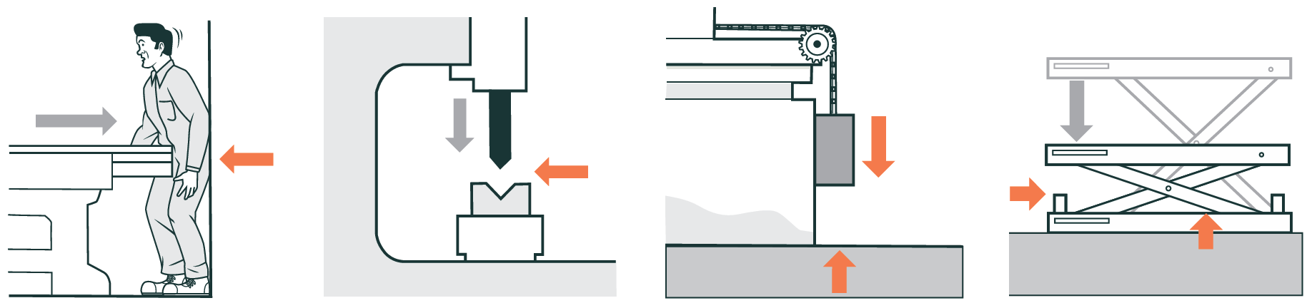
Impact hazards
Impact hazards are caused by objects that strike the body but do not enter it such as shown below.
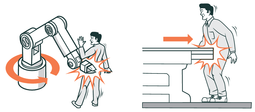
Friction and abrasion hazards
Friction burns can be caused by smooth parts operating at high speed. Examples of friction or abrasion hazards include:
- the sides of a grinding wheel
- the belt of a belt sanding machine
- material running onto a reel or shaft
- a conveyor belt and its drums
- pulleys and fast-moving ropes or belts.
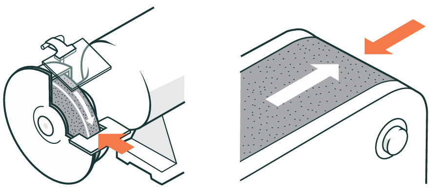
Entanglement hazards
Entanglement is when someone is caught in a machine by loose items (such as clothing, gloves, ties, jewellery, long hair, cleaning rags, bandages or rough material being fed into the machine).
Contact that can lead to entanglement includes:
- touching a single rotating surface (such as plain shafting, couplings, spindles, chucks, lead screws, mandrels or rotating work pieces including plain bar material)
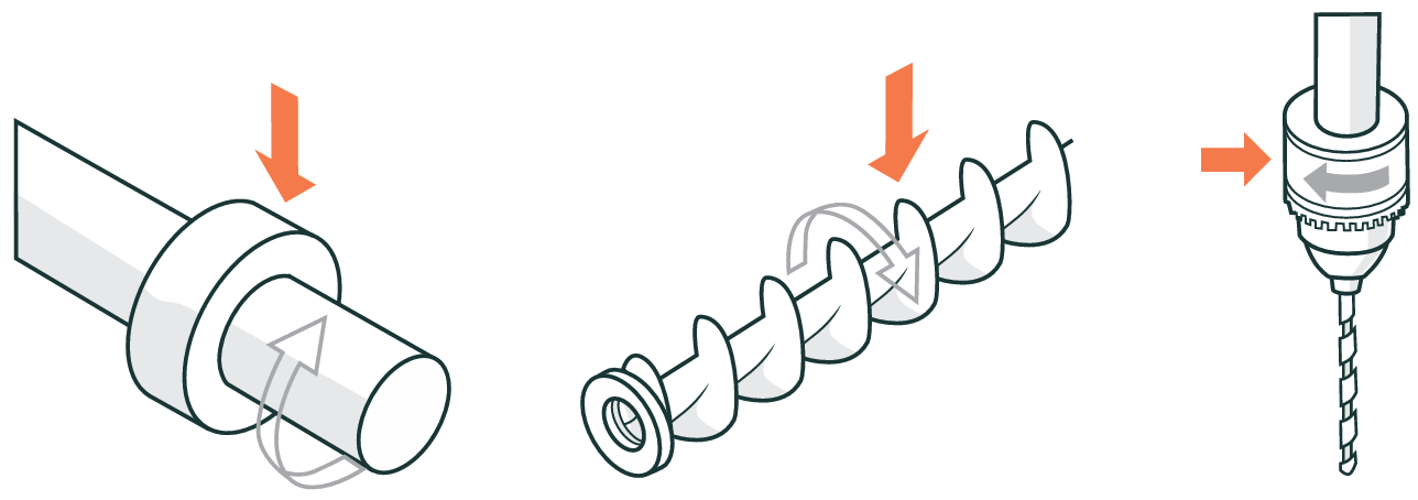
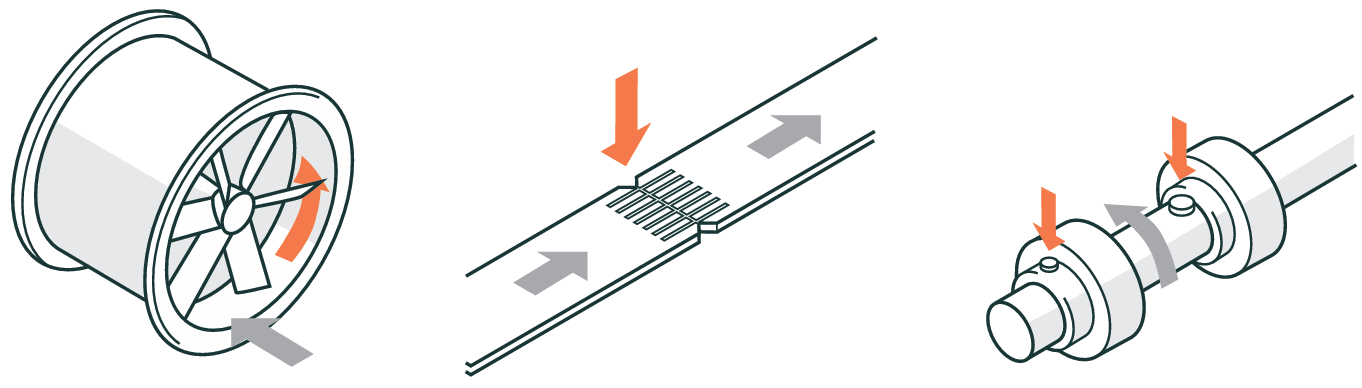
- catching on projections or in gaps. Belt fasteners and other projecting items (such as keys, set screws and cotter pins) are typical projection hazards. Fan blades, spoked wheels (such as pulleys, sprockets, gear wheels and flywheels), mixer and beater arms and spiked cylinders create gap-related hazard
- touching moving materials in motion (such as in centrifuges, tumble driers and dough mixers or swarf)
- reaching between counter rotating parts (such as gear wheels, rolling mills)
- reaching between a rotating part and another part moving along it (such as a power transmission belt and its pulley, a chain and chain wheel, a rack and pinion, a conveyor belt and any of its pulleys, a rope and its storage reel)
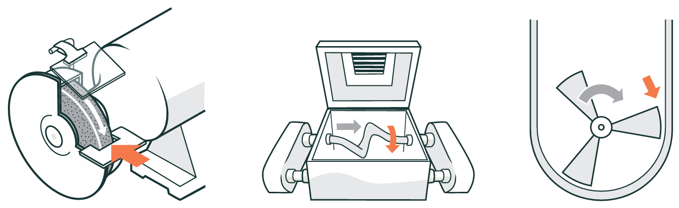
- reaching between rotating and fixed parts (such as flywheels and the machinery bed, screw or worm conveyors and their casings, mixers, extruder screw and barrel, the edge of an abrasive wheel, or an incorrectly adjusted work rest).
Shearing hazards
Shearing trims or shears metal (or other material) with a powered knife or slide.
Shear points are found where workpiece is inserted, held and withdrawn. The following figures show some ways operators can be injured by shearing hazards.
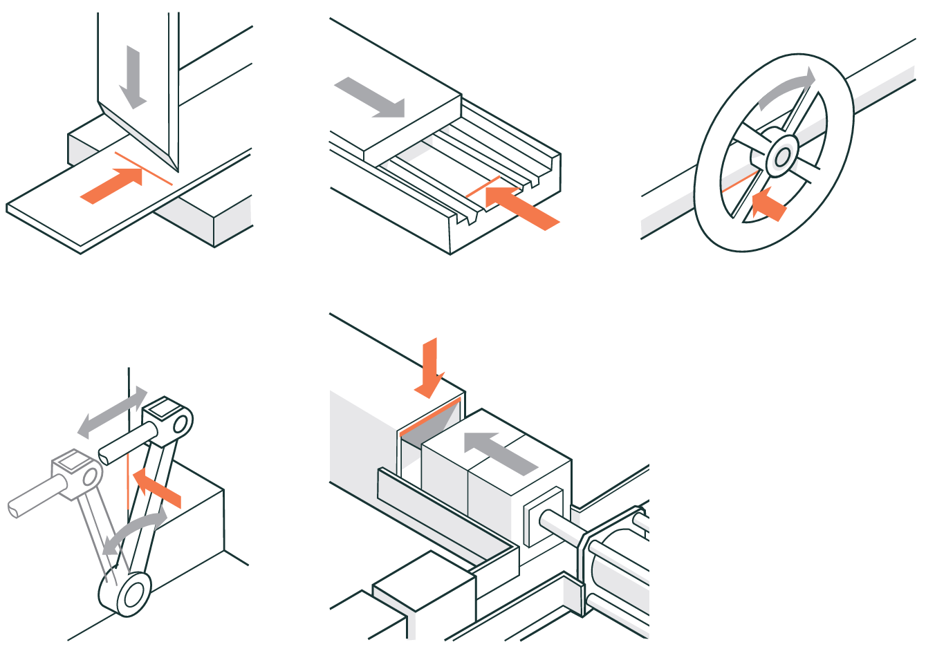
Cutting hazards
Cutting hazards exist at the point where wood, metal or other materials are cut.
Many kinds of tools create cutting hazards:
- band and circular saws
- boring or drilling machines
- planing and tenoning machines
- milling machines
- cutting edges of milling tools water jet cutting
- high energy lasers.
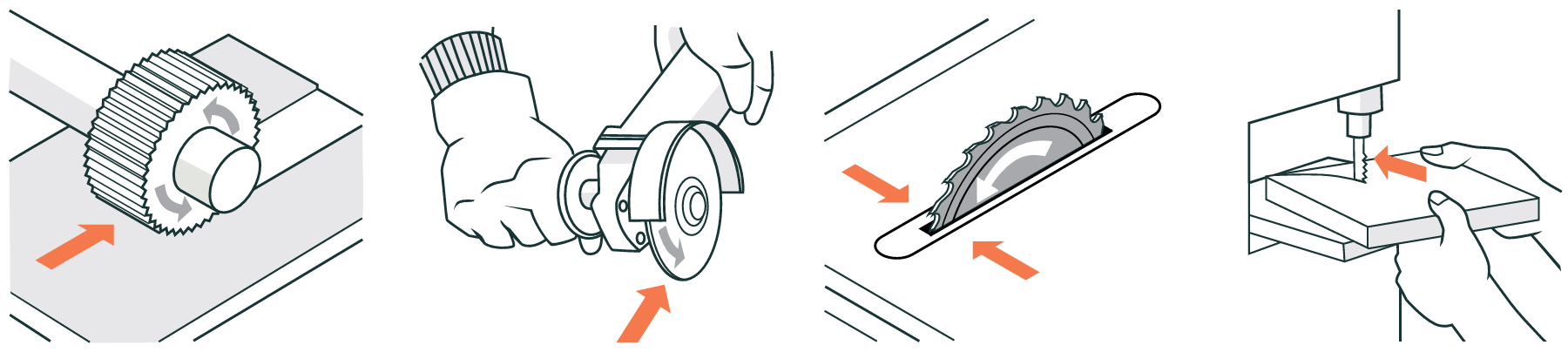
Stabbing and puncturing hazards
Operators can be injured by stabbing and puncturing hazards. These could include:
- a loose tool in a lathe
- broken tooling on a press or a CNC router
- an abrasive wheel breaking up
- swarf
- timber from a bench saw
- molten metal from a die-casting machine
- sparks from welding
- a bolt from an explosive powered tool
- debris thrown by rotary mowers and hedge cutters.
Operators can also be pierced by rapidly moving parts of machinery such as:
- the needle of a sewing machine
- the drill of a drilling machine
- the arm of a robot.
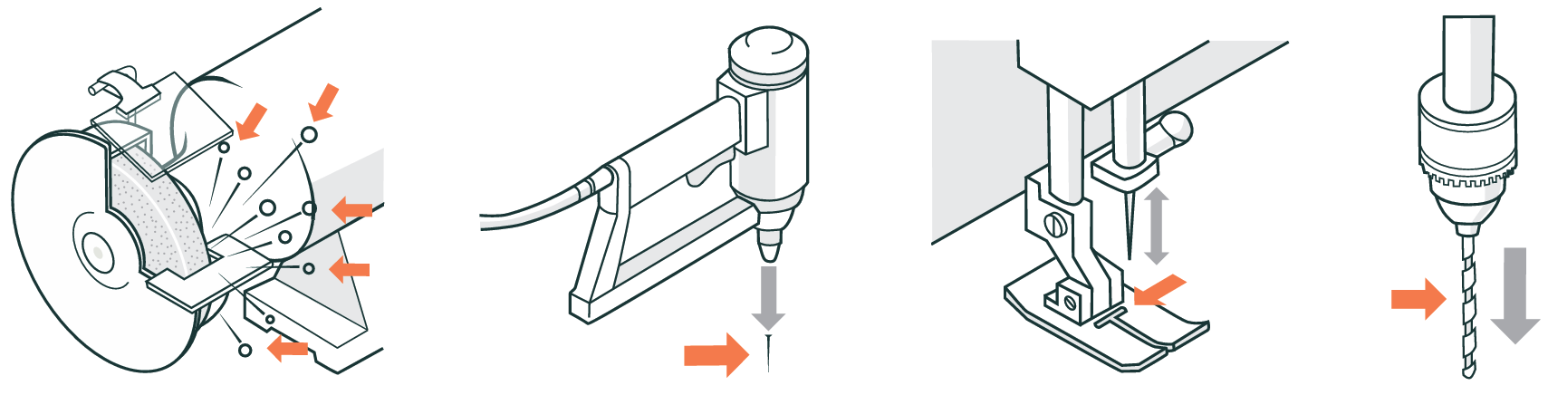
Appendix 5: Summary of the AS/NZS 4024.1–2019
Safety of Machinery series
AS/NZS 4024.1 2019 is the Australia/New Zealand Standard for managing machinery hazards. The standard is available in four series, shown below.
Organisation of AS 4024
Series 1, General safety requirements:
- Terminology and principles
- Risk assessment
- Design of safety-related parts of control systems
- Design of controls, interlocks and guarding
- Human body measurements
- Safety distance and safety gaps
- Ergonomic design of display and control actuators
- Indication marking and actuation
Series 2, Controls and approach speeds:
- Two-handed controls
- Approach speeds
Series 3, Requirements for specific machines:
- Mechanical power presses
- Hydraulic power presses
- Milling machines
- Industrial robots
Series 4, Electro-sensitive safety devices:
- Pressure sensitive devices
AS/NZS 4024.1–2019, Safety of Machinery series, has 26 parts under the eight headings in the diagram above. The 26 Parts are European (EN) and internationally based (ISO) safety and design standards with some modifications to meet New Zealand and Australia's safety practices and regulations.
The series gives designers, manufacturers, suppliers, employers and users of machinery guidelines to help reduce the risks of working with, or near machinery.
Designers, manufacturers, suppliers, employers and users of common manufacturing machinery not listed above can find specific guidance in:
- 4024.3610 to 4024.3612 Conveyors – Safety Requirements
- 1788.1 and 1788.2 (series) Abrasive Wheels
- 1473 (series) and ISO 19085-1 series Wood Processing Machinery.
People looking for more information about electro-sensitive safety devices (beyond what is in AS/NZS 4024 Series 4) should find it in IEC 61496 (series) Electro-sensitive Protective Equipment.
AS/NZS 4024.1–2019 Safety of machinery
Includes:
Safety principles
Terminology and principles
4024.1101 Terms and definitions
Gives users a set of terms and definitions that are used in other machinery safety standards, as well as in discussions of machinery safety.
4024.1201 Basic terminology and methodology
Specifies the basic terminology and methodology to be used by designers to achieve safety of machinery.
4024.1202 Technical principles
Defines the technical principles needed to design safe machinery. Does not deal with injury to domestic animals, property or the environment.
Risk assessment
4024.1301 Principles of risk assessment
Specifies principles for doing a risk assessment so the knowledge and experience of the harm related to machinery is gathered together to help assess risks during all phases in the life of machinery. Gives guidance on the information needed to carry out risk assessments and a brief outline of some of the techniques available.
4024.1302 Reduction of risks to health and safety from hazardous substances emitted by machinery – Principles and specification for machinery manufacturers
Gives principles for controlling risks to health from the emission of hazardous substances from machinery.
4024.1303 Risk assessment – Practical guidance and examples of methods
Ergonomic principles
4024.1401 Design principles – Terminology and general principles
Specifies the ergonomic design principles and terminology to be used by designers.
Design parameters
Design of safety-related parts of control systems
4024.1501 General principles
Gives safety requirements and guidance on the principles to be used in the design of the safety features of machinery control systems. Categories are specified and the characteristics of the safety functions are described.
4024.1502 Validation
Specifies the conditions and procedures to be followed for the validation by both analysis and testing of safety functions provided and safety category achieved by the safety-related parts of control systems using the design rationale, including risk analysis, provided by the designer. When validating programmable electronic systems, this standard does not give complete requirements and needs the use of other standards such as the AS 61508 series.
4024.1503 Safety related parts of control system – General principles of design
Design of controls, interlocks and guarding
4024.1601 Guards – General requirements for the design and construction of fixed and moveable guards
Specifies requirements for the design and construction of fixed and movable guards that protect people from mechanical hazards in machinery.
4024.1602 Principles for design and selection
Specifies principles for the design and selection of interlocking devices used with guards. The principles are independent of the energy sources used on the machine.
4024.1603 Prevention of unexpected start-up
Gives ways to stop unexpected machine start-up to use at the design stage, including energy isolation and dissipation. Applies to all forms of energy, including those external to the machine, such as wind, gravity and electro-magnetic.
4024.1604 Emergency stop – Principles for design
Explains what an emergency stop needs to do and gives the design principles, regardless of the energy source used to control the functions. It does not apply to hand-guided machines, hand-held portable machines or to machines where having an emergency stop would not reduce the risk to anyone.
Ergonomics
Human body measurements
4024.1701 Basic human body measurements for technological design
Gives information and descriptions of anthropometric (human body) measurements that ergonomists and designers of workplaces can use to compare population groups.
Use this standard to help design work stations where people stand, sit or reach controls or other items. There are pictures to help.
4024.1702 Principles for determining the dimensions required for openings for whole body access to machinery
Gives the smallest size an opening can be when someone has to go through it to access machinery. There may be extra requirements for mobile machinery.
Use this standard to help design openings, such as for people to walk upright through or climb via a vertical ladder. Sizes are also given for users wearing personal protective equipment or carrying an injured person.
4024.1703 Principles for determining the dimensions required for access openings
Gives minimum sizes for access openings in machinery. Additional space needs are also given. There may be extra requirements for mobile machinery.
Use this standard to help design access openings for putting body parts into a machine. It allows for different postures, such as standing or crouching.
4024.1704 Anthropometric data
Gives the human body measurements needed to calculate the size of access openings in machinery. The measurements come from European surveys. Use AS 4024.1701 for information on how to source human body measurements.
Safety distances and safety gaps
4024.1801 Safety distances to prevent danger zones being reached by the upper limbs
Gives the minimum safety distances between a barrier and a danger zone of a machine to stop anyone over three years old reaching the danger zone with their arms. Only use this standard when distance alone can remove the hazard. This standard does not protect against radiation or substances coming out of the machine.
4024.1802 Safety distances to prevent danger zones being reached by the lower limbs
Gives safety distances to keep people's legs out of danger zones of machinery. Only use these distances when distance alone can remove the hazard, and there is no chance that someone can reach the hazard with their arms.
4024.1803 Minimum gaps to prevent crushing of parts of the human body.
Gives minimum gaps in machinery to stop parts of the body being crushed.
Displays, controls, actuators and signals
Ergonomic requirements for the design of displays and control actuators
4024.1901 General principles for human interaction with displays and control actuators
Gives general principles to design displays and controls so operators can use the machine efficiently.
4024.1902 Displays
Gives the ergonomic requirements for visual, audible and tactile displays on machines. It helps you choose, design and place any displays to avoid ergonomic hazards.
4024.1903 Control actuators
Helps you design, choose and place manual control actuators to suit the needs of the task and the operators.
Indication, marking and actuation
4024.1904 Requirements for visual, auditory and tactile signs
Explains how to give safety information, using sight, sound and touch. It sets out a system of colours, signs, markings and other ways to show hazards and help in emergencies.
4024.1905 Requirements for marking
Gives rules on markings on machines for:
- identification
- safe use
- preventing hazards from incorrect connections.
4024.1906 Requirements for the location and operation of actuators
Gives the safety requirements for actuators run by hand or other body part. It applies to both single actuators and groups of actuators.
4024.1907 System of auditory and visual danger and information signals
Gives a series of danger and information signals (both sight and sound) that indicate urgency and can be differentiated from each other. This standard does not apply to signals covered by specific standards or conventions, such as fire alarms, public transport or navigation signals.
Position of two-hand controls and safety sensors
Two-hand control devices
4024.2601 Two-hand control devices – Principles for design and selection
Gives the safety requirements for two-hand controls.
This standard helps you design and choose two-hand control devices, using a risk assessment. It helps stop work-arounds and faults. It also gives standards for two-hand control devices with a programmable electronic system.
Safety distances and safety gaps
4024.2801 Safety distances and safety gaps – Positioning of protective equipment with respect to the approach speed of parts of the human body
Explains how to work out the minimum distances for sensing or actuating devices of protective equipment to a danger zone. The safety distances are based on hand or arm approach speeds and the response time of the machine.
These devices are:
- trip devices defined in AS 4024.1201 (specifically electro-sensitive protective equipment, pressure sensitive mats), including those used to start the machine
- two-hand control devices defined in AS 4024.1201.
Mechanical power presses
4024.3002 Materials forming and shearing – Mechanical power presses
Gives the safety requirements and measures to design, build and supply mechanical presses that work cold metal or material partly of cold metal. You can use the principles in 4024.1 for work with hot metal and tongs, but you might not be able to apply them fully. Read this standard with AS 4024.1 (series).
This standard also covers presses intended for work with cold metal but are used in a similar way to work other materials (like cardboard, plastic, rubber or leather) and metal powder.
The requirements in this standard take account of intended use. This standard presumes access to the press from all directions and gives the safety measures for both the operator and other people.
This standard also applies to accessories that are vital parts of the press.
Hydraulic power presses
4024.3002 Materials forming and shearing – Hydraulic power presses
Gives the safety requirements and measures for hydraulic presses that work cold metal or material partly of cold metal. You can use the principles in AS 4024.1 for work with hot metal and tongs, but you may not be able of apply them fully. Read this standard with AS 4024.1 (series).
This standard also covers presses intended for use with cold metal, but are also used in a similar way to work other sheet materials (like cardboard, plastic, rubber or leather) and metal powder.
The requirements in this standard take account of the intended use. This standard presumes access to the press from all directions, deals with the hazards and gives safety measures for the operator and other people.
This standard also applies to accessories that are vital to the press.
Milling machines (including boring machines)
4024.3101 Safety of machinery – Materials cutting – Milling machines (including boring machines) – Safety requirements
Gives the safety requirements and measures to design, build, supply, install, take apart, transport and maintain milling and boring machines.
Robots for industrial environments
4024.3301 Robots and robotic devices – Safety requirements for industrial robots
Gives requirements and guidelines to design, build and use industrial robots and robot systems safely. It describes some hazards of working with robots and how to avoid them.
While this standard does not cover non-industrial robots, the safety principles can be used for them. Non-industrial robot applications include:
- undersea
- military and space robots
- tele-operated manipulators
- prosthetics and other aids for the physically impaired
- micro-robots (smaller than 1 mm)
- surgery or healthcare
- service or consumer products.
4024.3302 Robots and robotic devices – Safety requirements for industrial robots – Robot systems and integration
4024.3303 Robots and robotic devices – Collaborative robots
AS/NZS 4024.4-1998 Safeguarding of machinery
Includes:
Pressure-sensitive devices
4024.4 Safeguarding of machinery – Installation and commissioning requirements for electro-sensitive systems – Pressure-sensitive devices
Explains the requirements to install and commission pressure-sensitive fixed mats, floors, edges and bars that will be used with plant and machinery.
You will need to adapt or extend this standard if safety devices are to be used in other situations, such as protecting children or in exposed places with wide temperature limits.
Appendix 6: Example risk assessment process
The process can be used to identify hazards, assess their risks and identify controls to implement in relation to safeguarding of machinery and plant. This risk management process is outlined below.
1. Identify potential hazards
These may include:
- drawing-in or trapping hazards
- entanglement hazards
- shearing hazards
- cutting hazards
- impact hazards
- crushing hazards
- stabbing and puncturing hazards
- friction and abrasion hazards
- hot or cold hazards
- ejection hazards
- other contact hazards
- noise hazards
- release of hazardous substances
- hazards related to location of the machine or plant
- hazards related to systems of work associated with the machine or plant
- concurrent hazards.
Questions to ask to identify hazards:
- Where fixed guards are provided, are they of substantial construction and secured into position while machinery is in operation?
- Where interlocked guards are provided, do they prevent operation of the machinery when open, and are the guards prevented from opening while the machinery is in operation?
- Where a presence-sensing system is used, does it operate as intended and stop the machinery when light beams or sensors are interrupted?
- Do guards protect against hazards at the rear and sides of machinery?
- Are pre-operational checks conducted to ensure safety features are in working order?
- Are adequate isolation procedures provided for maintenance?
- Are manufacturers' manuals available?
- Are machine controls protected to prevent unintentional operation, clearly marked and within easy reach of the operator?
- Are warning signs and decals clearly visible?
- Where it is not practical to provide guarding and people are required to operate or pass close to dangerous moving parts, is a safe system of work in place to reduce risks?
- Is it practical to provide a higher level of guarding than currently provided?
- Are operators and maintenance workers adequately trained, familiar with the operation and set up of machinery and able to demonstrate safety features?
2. Assess the level of risk for identified hazards
- Gather information about the hazard(s). Consult with relevant people, including workers.
- Work out the likelihood of an injury or harm occurring. Consider how many people are likely to be exposed to the hazard and for how long. Take into account different situations or conditions that might exist at the workplace and could increase risk, such as changes to operations, inspection, cleaning, maintenance, servicing and repairs and new or inexperienced workers.
- Use the information you have gathered to assess the potential consequences of any injury or harm occurring from the hazard(s); for example, whether people die or suffer major, minor or negligible injuries.
- Rate the risk by using the risk rating table below to work out the level of risk associated with each hazard.
3. Control measures
Once the risk has been assessed, where required, choose control measures to eliminate the risk. See section 4 of this guideline for options to control hazards.
4. Residual risk
The risk may then be assessed after taking into consideration how much the hazard controls will prevent harming workers.
| Likelihood of injury or harm to health | Consequences of injury or harm to health | |||
|---|---|---|---|---|
| Insignificant no injuries |
Moderate first aid and/or medical treatment |
Major extensive injuries |
Catastrophic fatalities |
|
| Very likely | High | Extreme | Extreme | Extreme |
| Likely | Moderate | High | Extreme | Extreme |
| Moderate | Low | High | Extreme | Extreme |
| Unlikely | Low | Moderate | High | Extreme |
| Highly unlikely (rare) | Low | Moderate | High | High |
Extreme = immediate action
Risk rating table
Appendix 7: Flowcharts
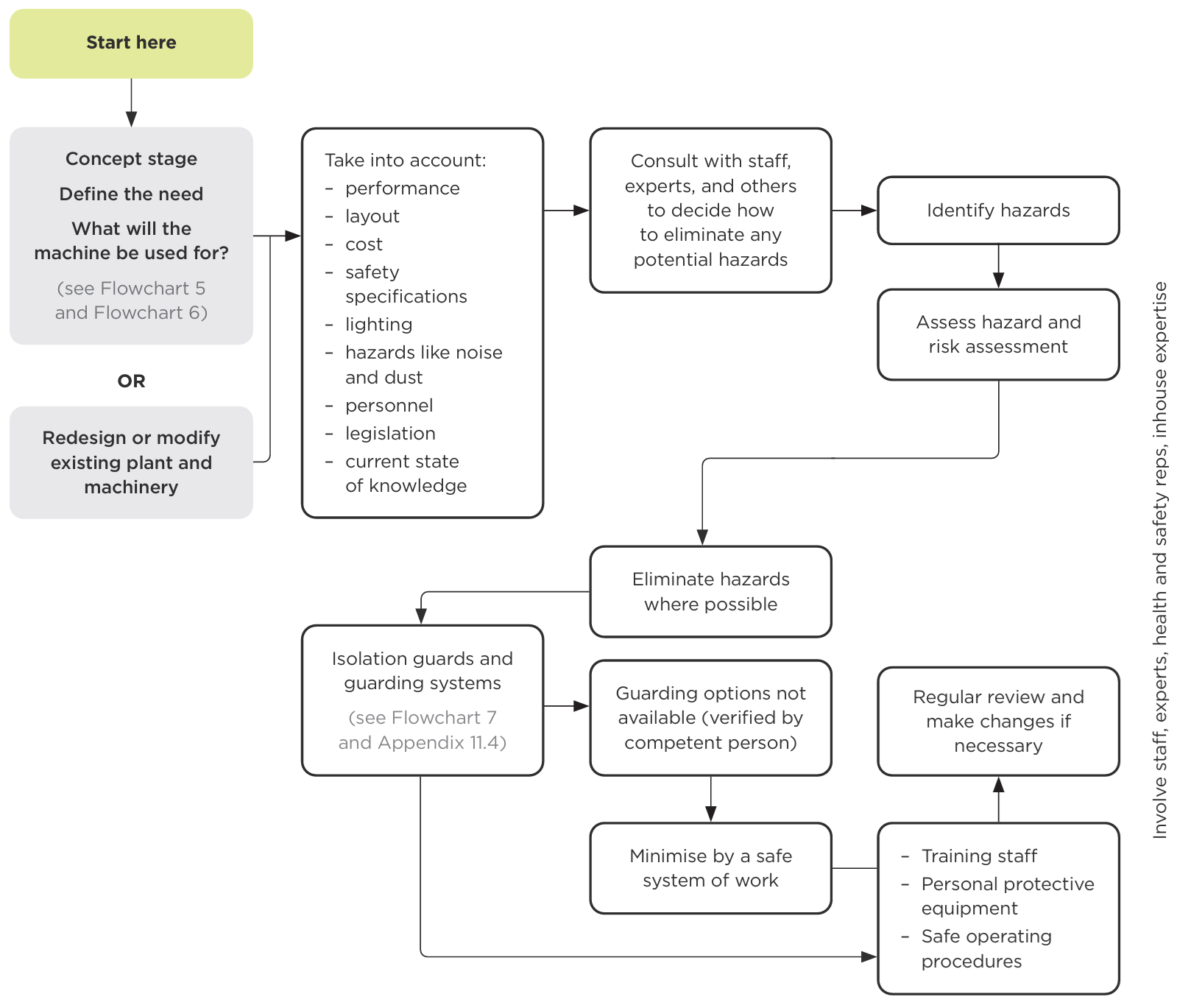
- Concept stage. Define the need. What will the machine be used for? (see Flowchart 5 and Flowchart 6) — Or — Redesign or modify existing plant and machinery.
- Take into account: performance, layout, cost, safety specifications, lighting, hazards like noise and dust, personnel, legislation, current state of knowledge.
- Consult with staff, experts, and others to decide how to eliminate any potential hazards.
- Identify hazards.
- Assess hazard and risk assessment.
- Eliminate hazards where possible.
- Isolation guards and guarding systems (see Flowchart 7 and Appendix 11.4).
- If guarding options are not available (verified by a competent person)
- minimise by a safe system of work
- Training staff, personal protective equipment, safe operating procedures.
- Regular review and make changes if necessary.
A side note running alongside the whole process reads: Involve staff, experts, health and safety reps, inhouse expertise.
End of text alternative.
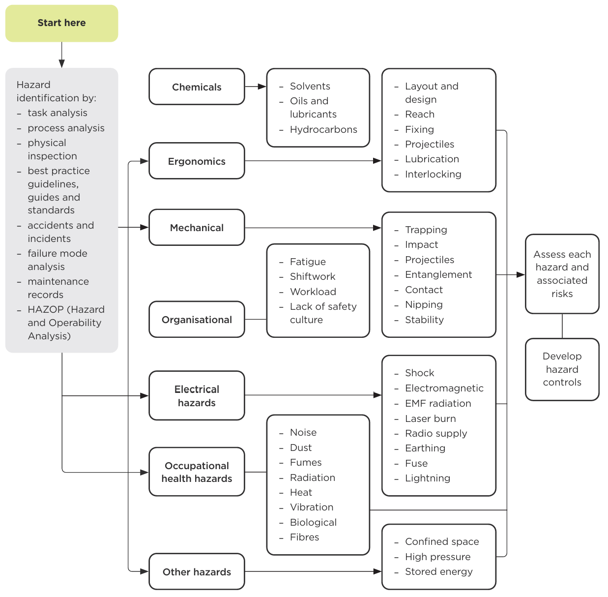
- Hazard identification by: task analysis, process analysis, physical inspection, best practice guidelines, guides and standards, accidents and incidents, failure mode analysis, maintenance records, HAZOP (Hazard and Operability Analysis).
- This feeds into seven hazard categories:
- Chemicals: solvents, oils and lubricants, hydrocarbons.
- Ergonomics: layout and design, reach, fixing, projectiles, lubrication, interlocking.
- Mechanical: trapping, impact, projectiles, entanglement, contact, nipping, stability.
- Organisational: fatigue, shiftwork, workload, lack of safety culture.
- Electrical hazards: shock, electromagnetic, EMF radiation, laser burn, radio supply, earthing, fuse, lightning.
- Occupational health hazards: noise, dust, fumes, radiation, heat, vibration, biological, fibres.
- Other hazards: confined space, high pressure, stored energy.
- Assess each hazard and associated risks.
- Develop hazard controls.
End of text alternative
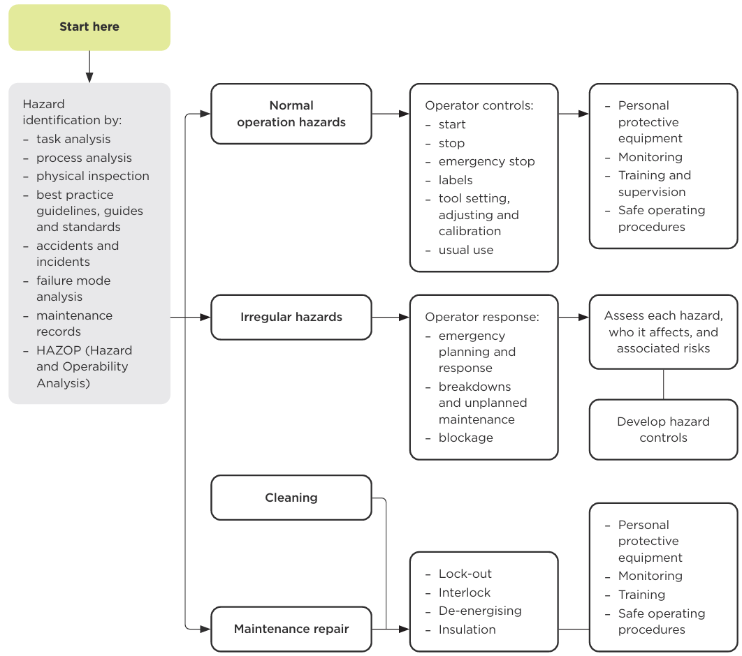
- Hazard identification by: task analysis, process analysis, physical inspection, best practice guidelines/guides and standards, accidents and incidents, failure mode analysis, maintenance records, HAZOP (Hazard and Operability Analysis).
- This flows into three hazard situations:
- Normal operation hazards.
- Operator controls: start, stop, emergency stop, labels, tool setting/adjusting/calibration, usual use.
- Personal protective equipment, monitoring, training and supervision, safe operating procedures.
- Irregular hazards.
- Operator response: emergency planning and response, breakdowns and unplanned maintenance, blockage.
- Assess each hazard, who it affects, and associated risks.
- Develop hazard controls.
- Maintenance repair. Together with Cleaning, this flows to:
- Lock-out, interlock, de-energising, insulation.
- Personal protective equipment, monitoring, training, safe operating procedures.
- Normal operation hazards.
End of text alternative
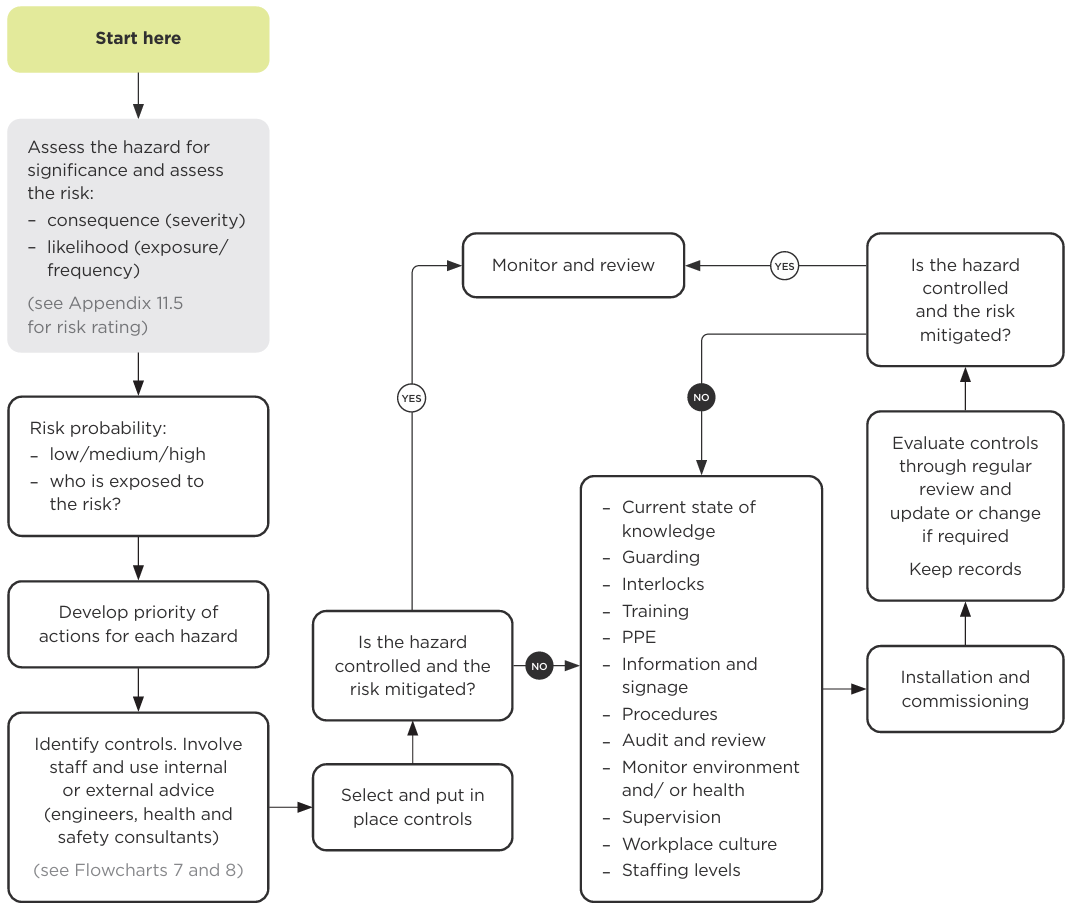
- Assess the hazard for significance and assess the risk: consequence (severity), likelihood (exposure/frequency) (see Appendix 11.5 for risk rating).
- Risk probability: low/medium/high, and who is exposed to the risk?
- Develop priority of actions for each hazard.
- Identify controls. Involve staff and use internal or external advice (engineers, health and safety consultants) (see Flowcharts 7 and 8).
- Select and put in place controls.
- Is the hazard controlled and the risk mitigated?
- No: current state of knowledge, guarding, interlocks, training, PPE, information and signage, procedures, audit and review, monitor environment and/or health, supervision, workplace culture, staffing levels.
- Installation and commissioning
- Evaluate controls through regular review and update or change if required. Keep records.
- Restart step 6.
- Yes: Monitor and review.
- No: current state of knowledge, guarding, interlocks, training, PPE, information and signage, procedures, audit and review, monitor environment and/or health, supervision, workplace culture, staffing levels.
End of text alternative.
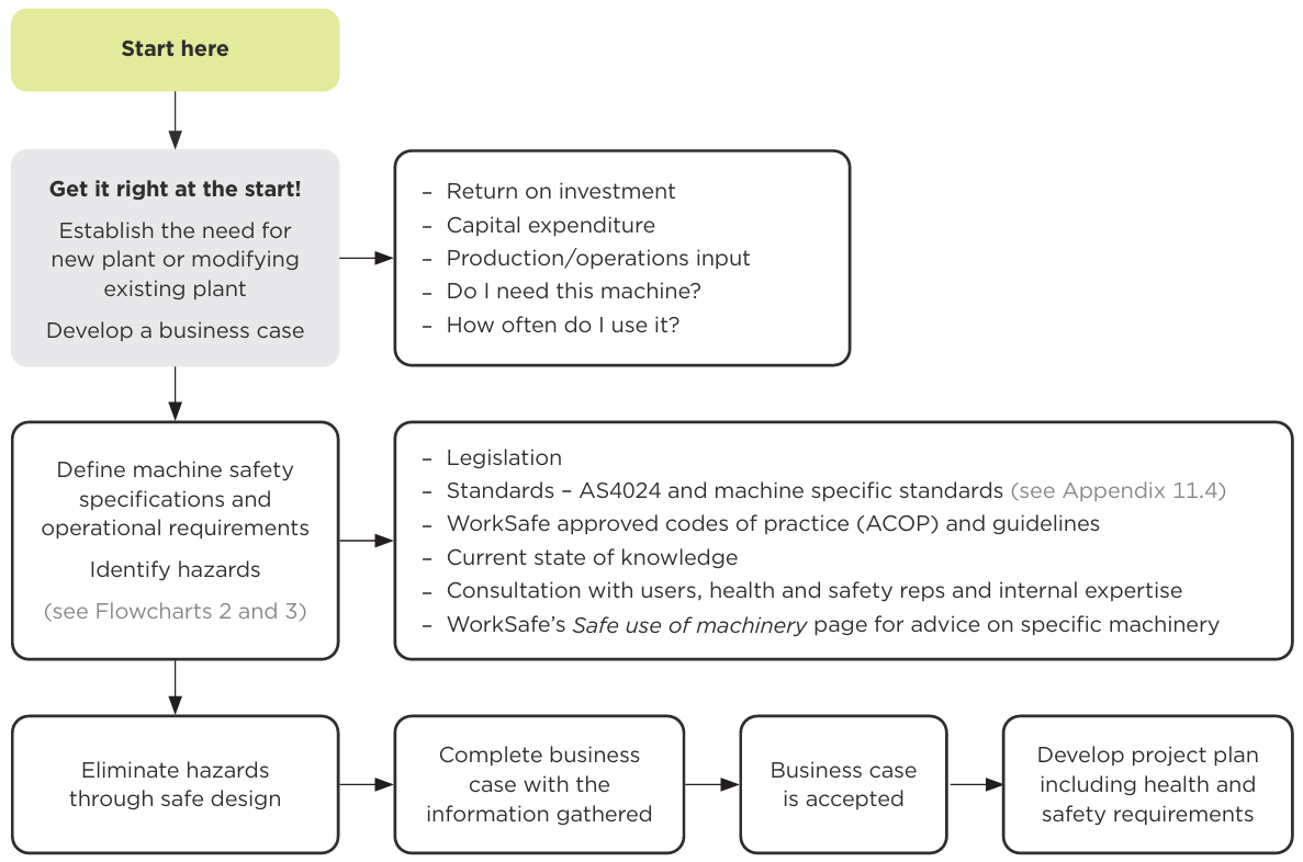
- Get it right at the start! Establish the need for new plant or modifying existing plant. Develop a business case.
- Return on investment, capital expenditure, production/operations input, Do I need this machine?, How often do I use it?
- Define machine safety specifications and operational requirements. Identify hazards (see Flowcharts 2 and 3)
- legislation; standards – AS4024 and machine-specific standards (see Appendix 11.4); WorkSafe approved codes of practice (ACOP) and guidelines; current state of knowledge; consultation with users, health and safety reps and internal expertise; WorkSafe's Safe use of machinery page for advice on specific machinery.
- Eliminate hazards through safe design.
- Complete business case with the information gathered.
- Business case is accepted.
- Develop project plan including health and safety requirements.
End of text alternative.
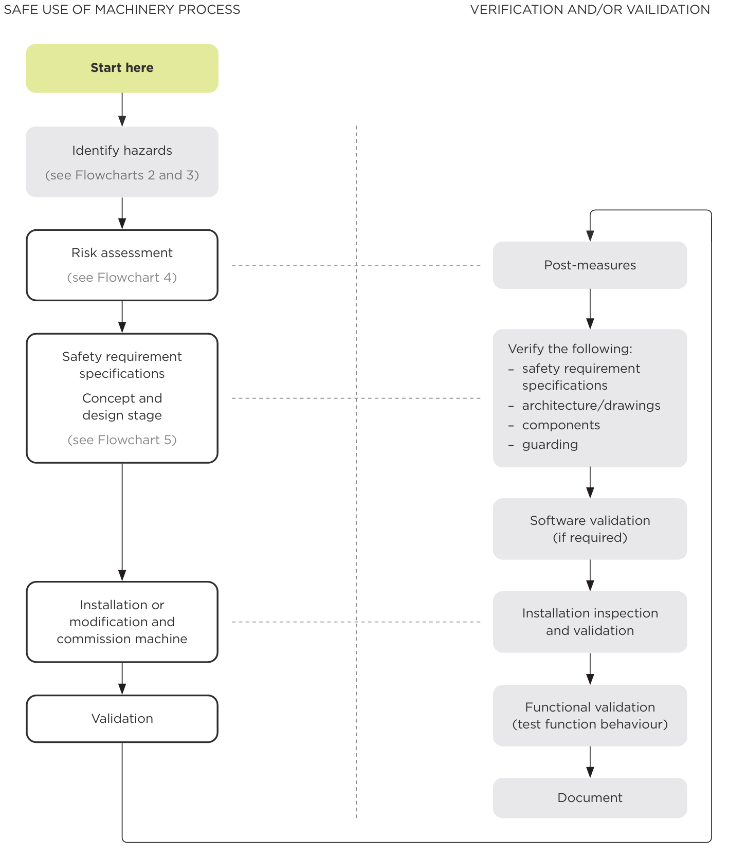
Safe use of machinery process:
- Identify hazards (see Flowcharts 2 and 3).
- Risk assessment (see Flowchart 4).
- Safety requirement specifications. Concept and design stage (see Flowchart 5).
- Installation or modification and commission machine.
- Validation.
Verification and/or validation:
- Post-measures
- Verify the following: safety requirement specifications, architecture/drawings, components, guarding.
- Software validation (if required).
- Installation inspection and validation.
- Functional validation (test function behaviour).
- Document.
End of text alternative.
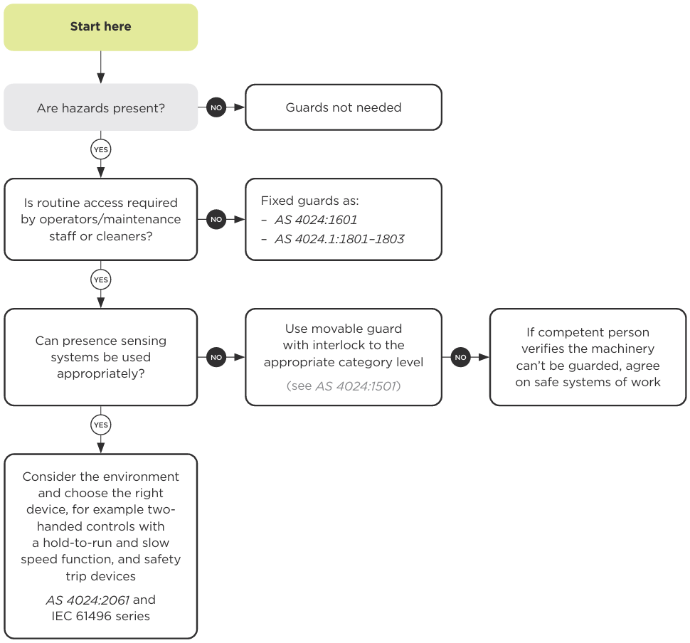
- Are hazards present?
- No: Guards not needed.
- Yes: continue.
- Is routine access required by operators/maintenance staff or cleaners?
- No: Use fixed guards as: AS 4024:1601 and AS 4024.1:1801–1803.
- Yes → continue.
- Can presence sensing systems be used appropriately?
- No: Use movable guard with interlock to the appropriate category level (see AS 4024:1501
- No: If competent person verifies the machinery can't be guarded, agree on safe systems of work.
- Yes: Consider the environment and choose the right device, for example two-handed controls with a hold-to-run and slow speed function, and safety trip devices. AS 4024:2061 and IEC 61496 series.
- No: Use movable guard with interlock to the appropriate category level (see AS 4024:1501
End of text alternative.
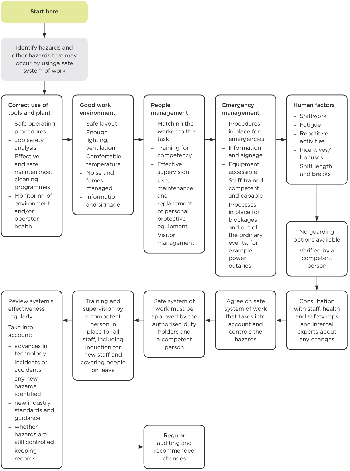
- Identify hazards and other hazards that may occur by using a safe system of work:
- Correct use of tools and plant: safe operating procedures, job safety analysis, effective and safe maintenance/cleaning programmes, monitoring of environment and/or operator health.
- Good work environment: safe layout, enough lighting/ventilation, comfortable temperature, noise and fumes managed, information and signage.
- People management: matching the worker to the task, training for competency, effective supervision, use/maintenance/replacement of personal protective equipment, visitor management.
- Emergency management: procedures in place for emergencies, information and signage, equipment accessible, staff trained/competent/capable, processes in place for blockages and out-of-the-ordinary events (for example, power outages).
- Human factors: shiftwork, fatigue, repetitive activities, incentives/bonuses, shift length and breaks.
- No guarding options available. Verified by a competent person.
- Consultation with staff, health and safety reps and internal experts about any changes.
- Agree on a safe system of work that takes into account and controls the hazards.
- Safe system of work must be approved by the authorised duty holders and a competent person.
- Training and supervision by a competent person is in place for all staff, including induction for new staff and covering people on leave.
- Review the system's effectiveness regularly, taking into account: advances in technology, incidents or accidents, any new hazards identified, new industry standards and guidance, whether hazards are still controlled, and keeping records.
- Regular auditing and recommended changes.
End of text alternative.
Last updated