On this page
- 6.1 Introduction to planning safe excavations
- 6.2 Terminology
- 6.3 Identifying whether ground or strata instability is a principal hazard
- 6.4 Geotechnical assessments for mining operations, A-grade quarrying operations and A-grade alluvial mining operations
- 6.5 Geotechnical advice for B-grade operations
- 6.6 PHMP for ground or strata instability
- 6.7 Slope design
- 6.8 Ground support and reinforcement systems
6.1 Introduction to planning safe excavations
A systematic approach to managing ground instability is very important.
When planning safe excavations, consider the unique characteristics of your site, the excavation method, and whether a geotechnical assessment should be done.
Planning also requires identifying hazards at your site, assessing risks and deciding suitable control measures often in consultation with workers and other PCBUs.
Ground conditions will significantly impact the excavation method you use and the control measures you put in place. The potential harm caused by unplanned and uncontrolled ground movements includes, but is not limited to:
- loss of life to workers or other people
- injuries to workers or other people
- collapse of, or damage to, nearby infrastructure
- interference with natural drainage and damage to surrounding land, natural habitats, wildlife or conservation initiatives and programmes
- unplanned failure of a slope occurring within proximity of a terminal boundary, encroaching on areas outside the approved area and breaching approval conditions
- loss of income, damaged business reputation, increased risk of prosecution
- disrupted operations, equipment losses, increased stripping and clean-up costs, lost customers, reduced business for your operation.
A geotechnical assessment can identify the type of ground conditions that exist at your site and tell you how these will most likely affect the ground stability of your operation.
In the planning phase, a competent person may be required to carry out a geotechnical assessment or provide geotechnical advice on ground conditions at your site. Information from the geotechnical assessment or advice will help you do an informed risk assessment and select appropriate control measures for your site. For more information on geotechnical assessments, see Sections 6.4 and 6.5.
6.2 Terminology
Slopes are generally designed as a series of batters separated by benches at predefined vertical height intervals (see Figure 4).
To keep a slope stable, make sure batter heights, bench widths, batter angles, inter-ramp slope height and slope angles are carefully designed.
![[image] 6.2 - fig 4 Slope design terminology](/assets/Topic/Extractives/Opencast-alluvial-mines-quarries/6.2-fig-4-slope-design-terminology.JPG)
Access to an excavation can be by a road or ramp, which may spiral around or be located on one side of the excavation with switchbacks at each end.
An inter-ramp slope is a series of batters between two access ramp sections or between a ramp section and the floor or crest.
The inter-ramp slope angle is always flatter than the batter angle in that slope.
The overall slope is the full height of a slope, from the toe to the crest, including several batters separated by benches (and access road sections if the road is on that slope). See Figure 5.
![[image] Figure 5: Slope design inter-ramp and overall slope details](/assets/Topic/Extractives/Opencast-alluvial-mines-quarries/6.2-fig-5-slope-design-inter-ramp-overall-slope-details.JPG)
6.3 Identifying whether ground or strata instability is a principal hazard
The responsible person (SSE, alluvial mine operator or quarry operator) must carry out an appraisal of the operation to identify whether ground or strata instability is a principal hazard at mining operations and A-grade operations. Complete the appraisal with a cross-section of the workforce, and any other skilled and experienced people who can provide input about the hazard, as required.
During the appraisal, consider how an excavation might possibly fail and the likely consequences of such a failure. The consequences will depend on the scale of the failure (the size of the failure and the area it affects) and whether people could be killed or injured.
If ground or strata instability is identified as a principal hazard at your operation, the responsible person must make sure a competent person completes a geotechnical assessment. For more information on geotechnical assessments for A-grade operations, see Section 6.4.
For B-grade operations, geotechnical advice must be obtained if there are high-risk working faces present at the operation. For more information on geotechnical advice for B-grade operations, see Section 6.5.
For mining operations and A-grade operations, a principal hazard is more likely to be present where:
- the height of any individual face is more than 15m
- there are soils and very weak rock where the height of any part of an excavation is more than 3.5m, and the overall slope angle is steeper than two horizontal to one vertical (27° to the horizontal) (see Figure 6)
- the bottom of the excavation is more than 30m below the surrounding ground level (see Figure 7)
- regardless of the excavation face height, depth or angle, other factors could create a principal hazard. For example, fractured rock mass or geological discontinuities (such as poor rock mass quality) or the location or proximity of a tip
- there is unweathered, high-strength rock and well-cemented gravels. A geotechnical assessment should be carried out where the overall:
- height of any adequately benched slope, from toe to crest, is between 15m and 30m
- slope angle is steeper than one horizontal to one vertical (1v:2h = 45° to the horizontal) (see Figure 7).
For more information on slope design, see Section 6.7.
![[image] 6.2 - fig 6 - 'Soils and very weak rock' guidance](/assets/Topic/Extractives/Opencast-alluvial-mines-quarries/6.2-fig-6-soils-very-weak-rock-guidance.JPG)
![[image] 6.2 - fig 7 - 'Stronger rock' guidance](/assets/Topic/Extractives/Opencast-alluvial-mines-quarries/6.2-fig-7-stronger-rock-guidance.JPG)
Soils and very weak rock definition
The definitions of very weak and extremely weak rock are shown in Table 1.
| Term | Field identification of specimen | Unconfined uniaxial compressive strength qu (MPa) | Point load strength Is(50) (MPA) |
| Very weak | Crumbles under firm blows with point of geological hammer | 1–5 | <1 |
| Extremely weak (also needs additional description in soil terminology) | Indented by thumbnail or other lesser strength terms used for soils | <1 | |
| Note: No correlation is implied between qu and Is(50) | |||
| Table 1: Definition of soils and very weak rock as defined by the New Zealand Geotechnical Society Incorporated Field Description of Soil Analysis Guideline (Dec 2005), Table 3.5 Rock Strength Terms | |||
Stronger rock definition
The definitions of stronger rock is shown in Table 2.
| Term | Field identification of specimen | Unconfined uniaxial compressive strength qu (MPa) | Point load strength Is(50) (MPA) |
| Extremely strong | Can only be chipped with geological hammer | >250 | >10 |
| Very strong | Requires many blows of geological hammer to break it | 100–250 | 5–10 |
| Strong | Requires more than one blow of geological hammer to break it | 50–100 | 2–5 |
| Moderately strong | Cannot be scraped or peeled with a pocketknife Can be broken with single firm blow of geological hammer | 20–50 | 1–2 |
| Weak | Can be peeled by a pocketknife with difficulty Shallow indentations made by firm blow with point of geological hammer | 5–20 | <1 |
| Note: No correlation is implied between qu and Is(50) | |||
| Table 2: Definition of stronger rock as defined by the New Zealand Geotechnical Society Incorporated Field Description of Soil Analysis Guideline (Dec 2005) Table 3.5 Rock Strength Terms | |||
6.4 Geotechnical assessments for mining operations, A-grade quarrying operations and A-grade alluvial mining operations
If ground or strata instability is identified as a principal hazard at a mining operation, A-grade quarrying operation or A-grade alluvial mining operation, the responsible person must make sure a competent person completes a geotechnical assessment to determine the level of ground or strata support needed to safely conduct the operation.
A geotechnical assessment of ground conditions is critical to developing a comprehensive PHMP.
The data collected during the assessment will be the foundation for:
- slope design and stability
- a suitable ground support system (where required)
- ongoing monitoring requirements suitable to the size and scale of slope design.
The geotechnical assessment should provide an indication of the risks and consequences of failure of your site. This may involve applying a factor of safety (FOS) calculation but could include more extensive probability analysis.
The geotechnical assessment should include information about:
- field data collection
- the geological features of the deposit, including:
- the strength of the rock mass
- hydrogeology
- the orientation of geological structures
- formulation of a geotechnical model
- slope design, including the design of bench heights and bench widths, taking into account the excavation method and equipment
- the probability of failure or the factor of safety (FOS) of the overall excavation
- how to position the quarry faces for stability during blasting and excavation, including consideration of failure modes and how they will be managed
- the suitability of the design for short and long-term stability, and for maintenance of the faces
- the design of adequate space for haul roads, with provision for safety features as necessary, for example:
- suitable road widths
- inner rock trap and berms
- outer edge protection (windrow)
- face edge stand-off
- design, control and monitoring of blasting
- design, installation and quality control of rock support
- design of suitable monitoring systems
- inspection and monitoring requirements.
The geotechnical assessment may also include information about:
- possible seismic (natural or induced) or geothermal activity
- previously excavated or abandoned workings
- subsidence or settlement
- equipment and procedures used for scaling (cleaning)
- the effects of time and oxidation on ground support and stability
- geotechnical design life requirements during and after extraction.
Field data collection
Field data includes all the information which might affect the design, construction and performance of excavations such as:
- site history
- topography and geomorphology
- local climate
- hydrogeology and drainage
- physical geology and geologic structure
- lithology and rock mass properties.
Field data should be collected by a competent person, or a trained geotechnician who is supervised by an engineering geologist or geotechnical engineer.
There are several tools and techniques available for field data collection. These include:
- surface geophysical data collection methods which provide initial identification of major lithological units and structural features, such as fracture zones
- downhole geophysics or logging that provide data to determine lithological boundaries, structures and the in-situ mechanical, physical and chemical properties of the rock mass
- core drilling which enables an adequate understanding of the subsurface conditions for input to geotechnical design. The number of boreholes required depends on:
- the level and reliability of already available geological and geotechnical information
- the complexity of site geology
- the size and operating life of the quarry or mine.
- core samples retrieved from boreholes which can be logged using direct observation, or with downhole cameras and digital photography
- field testing: geotechnical data collection from exposed rock can be carried out using 3D digital photogrammetric techniques
- laboratory testing: rock samples can be tested in a laboratory to determine intact rock properties.
6.5 Geotechnical advice for B-grade operations
A B-grade quarry operator or a B-Grade alluvial mine operator must obtain geotechnical advice from a competent person about any high-risk working face at the operation. A high-risk working face is one that:
- is at least 15m high, or
- poses a significant risk to workers as a result of one or more of the following factors:
- the height of the working face
- the ground type at the base of the working face
- the angle of the working face’s slope
- the strength of the rock on the working face
- the composition of the rock on the working face
- the geological structure of the working face
- the bedding surfaces of the working face
- the presence of water (for example groundwater or surface ponding) on or around the working face, or
- is part of an excavation that, at its deepest, is more than 30m below the surrounding ground level.
B-grade operators should take geotechnical advice into account when developing, documenting, implementing, and maintaining the operation’s health and safety management system (HSMS). After receiving geotechnical advice, a more detailed geotechnical assessment may be needed.
6.6 PHMP for ground or strata instability
At a mining operation, A-grade quarrying operation or A-grade alluvial mining operation, if ground or strata instability is identified as a principal hazard, the responsible person must develop a principal hazard management plan (PHMP). For general information about PHMPs, see Section 2.6.
Developing a PHMP
A PHMP should be developed in the context of your site’s HSMS, not separate to it. This will help to identify gaps and overlaps when implementing control measures at your site.
For a full list of requirements for a PHMP, see Regulation 68 of the MOQO Regulations.
For PHMPs specifically for ground or strata instability, see Regulations 71, 117, 118 and 131 of the MOQO Regulations for the requirements.
Assessing the risks
A PHMP must include details of the risk assessment for the principal hazard – in this case, ground or strata instability. Workers should be involved in this process.
Table 3 shows some of the things to consider when carrying out a risk assessment for ground or strata instabilities.
| Variable | Considerations |
| Structure of the rock mass | Such as folding, faulting, strikes and dips |
| Rock strength | Such as ‘very strong’ or ‘very weak’ rock |
| Slope type | Active or inactive |
| Slope geometry | Overall slope height, slope angle, bench height, bench slope angle and bench width |
| Slope material characteristics (including alteration grade) | Rock or soil, structurally controlled, variable alteration or materials present, material or discontinuity shear strength parameters |
| Soil | Type, contaminated or non-contaminated |
| Proximity of existing structures | Property or services adjacent to both crest and toe of slope, both external and located on site |
| Proximity of workers at the site | Vulnerability, location relative to potential failure |
| Proximity of other people at the site | Proximity of public access, roads, footpaths and walkways |
| Failure mechanism | Rockfall, planar, wedge, toppling, rotational, flow and travel distance |
| Speed of failure | Rapid (flows, rockfall), slow (rotational), very slow (rotational) |
| Water (surface water and groundwater) | Visible signs of seepage or discharge, prevention of detrimental effects by effective surface water management |
| Past history of failure | History of instability (such as type, location), visible signs of active or previous failure (such as bulging slope surfaces) |
| Existing remedial measures | Bolting, regrading and pumping (dewatering) |
| Monitoring | Extensometers, piezometers, closure meters, Electronic Distance Measurement targets, radar |
| Seismic history | Frequency of earthquakes in the region, liquefaction and rockfalls |
| Operating variables | Exposure time of workers (duration of shift), excavation method, associated equipment (vehicle) exposure, effects of poor blasting |
| Table 3: Key considerations for risk assessments for ground or strata instabilities | |
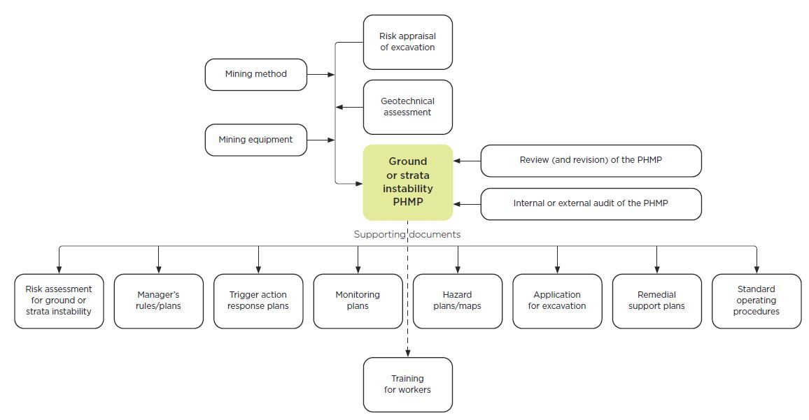
Figure 8 shows what should be included when developing and maintaining a ground or strata instability PHMP. For more information on managing instability, see Ground or strata instability in underground mines and tunnels
6.7 Slope design
Slope designs should be suitable for the ground conditions of the site and, where necessary, include ground support or reinforcement.
There is a tendency to increase the slope angle to decrease waste rock stripping and try to generate a higher return on investment. But increasing the slope angle will weaken the stability of the slope potentially leading to slope failure.
By applying sound geotechnical engineering practices, safe slopes can be designed and maintained in almost any geological environment. An important consideration for designing slopes is the full life cycle of the slope including abandonment.
Varying parameters of bench height, bench width, batter face angle, and interramp slope height and slope angle all contribute to improve overall slope stability. This section provides examples of these.
Slope stability analysis and factor of safety
Fundamental to slope stability analysis are the anticipated modes of failure, the scale of the slope, available data and the perceived risk relevant to the particular stage of the slope.
Whether a particular failure is ‘acceptable’ depends on its consequence and risk. If the failure of a particular slope has no bearing on its surroundings or safety and production, it is likely to be of minimal concern.
Slope design is governed by two factors: the consequence of failure and the degree of inherent uncertainty. It is good practice to apply a factor of safety (FOS) or probability of failure (POF) to the design. When the consequences of failure or the level of uncertainty are high, the design criteria should be altered accordingly (to a move conservative design). An example of the FOS and POF design criteria approach is shown in Table 4.
| Wall class | Consequence of failure | Design FOS | Design POF | Examples |
| 1 | Moderately serious | 1.2 | 10% | Highwalls not carrying major infrastructure |
| 2 | Serious | 1.5 | 1% | Highwalls carrying major infrastructure (for example, treatment plant, run-of-mine (ROM) pad, tailings structures, crushing structures) |
| 3 | Serious (where a mutually acceptable agreement to allow excavation cannot be made between the quarry or mine owner and the ‘owner’ of the adjoining structure or plot of land) | 2.0 | 0.3% | Permanent highwalls near public infrastructure and adjoining leases |
| Table 4: Example of FOS and POF design criteria approach | ||||
TYPES OF ANALYSIS
When developing stability analysis criteria, it is critical to understand the origins and limitations of the various geotechnical engineering design procedures.
You should also acknowledge that there are risks that can be created by unexpected conditions.
Examples of analysis methods include:
- rock mass rating (RMR) and mining rock mass rating (MRMR) classification systems
- kinematic analysis of structurally controlled failures
- limit equilibrium analysis
- numerical analysis.
Modes of failure
Collecting and interpreting information about major structures and other geological features is important in determining their potential for failure.
Steeper and higher slopes or batters will generate greater driving forces. This increases the potential for rock mass failure and presents a higher risk. Slopes or batters excavated within rock masses that contain persistent geological structures have greater potential to develop large-scale wall failures.
It is more important (and usually more difficult) to control large slope failures than small slope failures. Control measures for a large slope failure include:
- excavating slopes or batters to a shallower angle
- depressurisation of groundwater in the rock mass
- installing ground support and reinforcement.
Basic modes of failures are listed here.
Planar failures occur when a geological discontinuity, such as a bedding plane, strikes parallel to the slope face and dips into the excavation at an angle steeper than the angle of friction.
![[image] 6.7 - fig 9 - Planar failure](/assets/Topic/Extractives/Opencast-alluvial-mines-quarries/6.7-fig-9-planar-failure.JPG)
Wedge failures occur when two discontinuities intersect and their line of intersection daylights in the face.
![[image] 6.7 - fig 10 - Wedge failure](/assets/Topic/Extractives/Opencast-alluvial-mines-quarries/6.7-fig-10-wedge-failure.JPG)
Step-path failure is similar to planar failure, but the sliding is due to the combined mechanisms of multiple discontinuities or the tensile failure of the intact rock connecting members of the master joint set.
![[image] 6.7 - fig 11 - Step-path failure](/assets/Topic/Extractives/Opencast-alluvial-mines-quarries/6.7-fig-11-step-path-failure.JPG)
Ravelling is the weathering of material and the expansion and contraction associated with freeze-thaw cycles are the main causes of ravelling. This type of failure generally produces small rockfalls, not large failures.
![[image] 6.7 - fig 12 - Ravelling failure](/assets/Topic/Extractives/Opencast-alluvial-mines-quarries/6.7-fig-12-ravelling-failure.JPG)
Toppling can occur when vertical or near-vertical structures dip toward the pit. In this case, the bench face height should be limited to a distance roughly equal to the bench width. This will help catch any toppling material and reduce the chances of it hitting workers on the pit floor.
![[image] 6.7 - fig 13 - Toppling failure](/assets/Topic/Extractives/Opencast-alluvial-mines-quarries/6.7-fig-13-toppling-failure.JPG)
Circular failures (or slumps) occur in weak rock or soil slopes. They do not necessarily occur along a purely circular arc, but some form of curved failure surface is usual. Failures can occur at the surface (slope failure), at the toe (toe failure), or at depth in a weak zone.
![[image] 6.7 - fig 14 - Circular failure](/assets/Topic/Extractives/Opencast-alluvial-mines-quarries/6.7-fig-14-circular-failure.JPG)
Batter and final bench design
BATTER HEIGHT AND REACH
The height of batters should be determined on an individual basis, based on past extraction conditions of the seam or area, and sound engineering practices.
Maximum batter height should be based on:
- the recommendations of a competent person
- reliability of the batter design (that is, stability under potential failure modes)
- availability of equipment for adequate scaling to remove loose piece of rock.
Batter height should not exceed the safe reach of the equipment available to clean (scale) the face, unless control measures are in place. These control measures could include:
- blasting practices that shoot the face clean
- using mobile plant or equipment capable of working a safe distance from the toe while removing material to the toe
- using mobile plant or equipment to clean the face from the top edge.
BENCH SPACING
Where a slope contains many discontinuities (such as joint sets or bedding planes), having benches at select spacings can increase the stability of the slope.
Benches should be wide enough to stop potentially hazardous rock falls and contain any spills from the batters above from falling into the excavation and harming workers.
Where there is minimum space between benches and small-size rill material is still not contained, review your control measures. Be prepared to revise them to stop material falling into the excavation and workers being exposed to harm.
Control measures to consider:
- providing a bench or additional benches in the slope
- widening bench widths
- modifying blasting techniques
- changing the orientation of mining or extraction
- more effective cleaning methods.
BENCH WIDTHS
The width of benches is determined by several factors.
- If no other control measures are in place (such as rock fences), the bench should be wide enough to stop rockfalls and contain any material that falls from the wall above the bench.
- Extended exposure of the wall can cause rilling material to accumulate on the bench. Cleaning may be needed to maintain the bench’s effectiveness. When cleaning benches, the bench width should accommodate any equipment used on it. Safe access to the bench must be provided.
- Bench widths should allow for adequate drainage.
When designing bench widths, consider the likelihood of achieving the design width. Even with good blasting and excavation control, the design may not be achieved.
The width that can practically be achieved depends on the amount of back-break along the crest during excavation. Back-break from blasting can extend into the bench as much as three meters. Presplitting can reduce back-break if the holes are spaced close enough and plugged as near to the top of the hole as possible. This reduces the amount of stemming.
Consult an explosives contractor or supplier about other techniques that can be used to safely manage back-break.
The design of bench widths must also allow adequate space for haul roads with inner rock trap and berm, windrows, and face edge stand-off.
Working bench widths
To determine working bench widths, consider the type of equipment and the method of extraction. Make sure there is enough room to allow:
- exclusion zones to be set up where there are unsafe ground conditions
- bench access to be a suitable distance from the batter face
- excavating mobile plant to work
- trucks to queue safely while waiting to be loaded
- trucks being positioned correctly and safely during loading.
Do not allow workers or other people near hazardous batters or benches. Unsafe ground conditions should be dealt with immediately and corrected or treated as an exclusion zone.
Overall slopes
The methods of analysis for the design of overall slopes are the same as those for batter design, except the scale is different.
In stronger rocks, overall slopes may fail by planar and wedge sliding. In soils and weak rocks, they may fail by toppling and rotational shearing.
More complex collapses involving failure through the rock mass will require analysis by numerical methods.
Batter stability immediately below and above the access ramp should also be considered when designing inter-ramp slopes. Batter instability immediately below could undermine the ramp and instability immediately above could spill onto the ramp.
Groundwater and surface water control
Mines or quarries excavated below the groundwater table may need dewatering and depressurisation. The most significant problem is the effect water pressure has on slope stability. Water pressure in structural defects in the rock mass and pore spaces in rock material reduces effective stress and, consequently, shear strength.
At some sites with minor groundwater inflow from slopes or floor, dewatering may occur simply through evaporation. At other sites, major pumping operations may be necessary. Groundwater can also be controlled with methods such as:
- production bores (used before and during extraction)
- sumps or trenches
- sub-horizontal drainage holes drilled into the slopes.
Each method can be used individually or in combination. The most appropriate method for your site will depend on:
- local and regional hydrogeological conditions
- the relative importance of depressurisation to the specified design, and
- the required rate of production.
At large sites, all three methods may be needed to control groundwater.
Where complex groundwater issues could have a direct impact on ground stability, this may require input from an engineer specialising in geohydrology.
Control of surface water drainage is also an important aspect of slope design.
Surface water drainage paths through and around the site should be designed, constructed and maintained so water does not pond at the crest or toe of critical slopes.
To stop scouring on a face, do not discharge water over a face except in a single controlled point. If possible, the water should be directed along the bench to the roadway and along an open drain to a collection point, sump or settling pond.
6.8 Ground support and reinforcement systems
Ground support generally includes rock or cable bolts installed in the ground. Reinforcement systems (artificial support) can include retaining walls, drilled or cast in-place piles, earth and rock anchors, or reinforced earth.
Responsibilities for ground or strata support
The manager of the operation must make sure that:
- suitable ground or strata support or stabilisation systems are designed and used in all working areas, as required by Regulation 117 of the MOQO Regulations
- plans showing the ground or strata support or slope stabilisation arrangements are displayed where workers can easily access them.
Installing ground or strata support
A relevant operator must make sure that:
- no person enters areas with unsupported or unstable ground unless they are:
- installing or supervising ground or strata support
- carrying out or supervising slope stabilisation work
- temporary support is provided to keep workers safe when:
- installing or supervising the installation of ground or strata support
- carrying out or supervising slope stabilisation work.
Design considerations
When designing a ground support and reinforcement system, it should match the ground conditions of your site. Also consider:
- the function of the support (such as to prevent rock fall, slope failure or rockslides)
- the geological structure in and around the slope
- in-situ rock mass strength and behaviour of the rock support or reinforcement system under load
- groundwater regime and chemistry, rock stress levels and the changes in rock stress during the life of the excavation
- the potential for seismic events such as earthquakes or blasting
- retaining the overall factor of safety.
TIMING OF INSTALLATION
Generally, the earlier ground support is installed, the more effective it is.
Install the system as soon as practicable to limit potential loosening and unravelling of the rock mass. Long delays in installation may weaken the system’s effectiveness.
Ideally, potentially unstable wedges or blocks should be secured as excavation continues, with ground support being progressively installed.
CORROSION
Due to corrosion, no ground support system will last indefinitely. Using galvanised components may prolong its usefulness.
QUALITY CONTROL
Each element or layer of artificial support should be combined so that the overall system is well matched to the ground conditions for the design life of the excavation.
Develop a quality control procedure to make sure the standard of installation of artificial support meets the design expectations for all ground conditions at the site.
Artificial support measures
Artificial support can be categorised into four main groups:
- rock bolting systems
- retaining type structures
- surface treatments
- buttressing.
Table 5 details these four categories of artificial support measures.
| Type of support | Description |
|
Rock bolting systems Rock bolting systems typically fall into three categories: rock bolts, dowels (shear pins) and cable bolts. These systems can be improved by connecting individual components by welded mesh or strapping. |
|
| Rock bolts |
Tensioned once anchorage is achieved, to actively set up a compressive force into the surrounding rock. This axial force increases the shear capacity and is generated by pre-tensioning of the bolt. In essence, rock bolts start to support the rock as soon as they are tensioned. Commercially available rock bolts include cone and shell, grouted and chemically (resin) anchored rebar. |
| Rock dowels |
Can be used instead of rock bolts, when installation of support can be carried out very close to the excavated face or in anticipation of stress changes that will occur at a later excavation stage. Rock dowels are passive reinforcements that need some ground displacement for activation. |
| Cable bolting |
An established technique used extensively for reinforcement of the rock mass adjacent to surface excavations. They can be tensioned or un-tensioned and may be fully or partially grouted. Thread-bar rock anchors or multi-strand tendon cable anchors can be used where higher loads are required. |
| Shear pins |
Reinforcement bars or larger steel, concrete or post sections that may be grouted in situ. They are designed to be placed perpendicular to a particular discontinuity and to act mainly in shear. The support provided by the shear pin is equal to the shear strength of the steel bar and possibly the cohesion of the rock/concrete surface. Although shear pins are mainly installed perpendicular to the potential slide plane, there are some other applications. These can involve horizontal installations to provide shear support to blocks defined by flat-lying underground workings intersecting the pit wall, or unstable clay seams within an eroded rock wall. |
| Mesh |
Where bolting alone is insufficient and support is required for small, fractured material, welded or arc mesh secured to the rock bolts, dowels or cable bolts is a suitable form of support. Usually, a 100mm x 100mm mesh is used, but the size is determined by the desired bag strength. The use of mesh in very blocky ground reduces the potential for unravelling and can be a very useful ground support method. |
| W strapping | Used to connect the collars of rock bolts. They are nominally 2–3mm thick and 200-300mm wide and can be bolted to follow the contours of the rock face. Support tension can be exerted between bolt sets through the strap. |
|
Retaining type structures Retaining walls are typically formed from precast concrete or in situ poured concrete, steel sheet piling or bored piles. Walls can be reinforced or un-reinforced and can be tied back with tendons into the rock. Proper drainage behind the wall is critical to their performance. Drainage material will reduce or eliminate the hydraulic pressure and increase the stability of the fill material behind the wall. |
|
| Gabion walls | A traditional, effective and practical means of stabilising cuts and slopes. As they apply a surcharge load to the underlying pit wall, they must be installed upwards from a location where there is strong enough rock for a suitable foundation. |
| Stacked tyres | An alternative to gabions and may be simpler and cheaper to install. Each stack of tyres should be filled and secured. |
| Reinforced earth | Retaining walls are gravity structures consisting of alternating layers of granular backfill and reinforcing strips with a modular precast concrete facing. Because of their high load-carrying capacity, reinforced earth is ideal for very high or heavy-loaded retaining walls. |
| Tied-back walls | These generally comprise a concrete wall, often reinforced with mesh or reinforcement bars tied back into the rock wall using cable bolts, or rock bolts in smaller structures. These walls are particularly suited to mining applications where they can be constructed progressively as the benches are mined, using cable bolting meshing and a shotcrete application. |
| Steel sheet piling | Often used in soft soils and tight spaces. They are made of steel, vinyl, fibreglass or plastic sheet piles driven into the ground and can require a tie-back anchor ‘dead man’ tied by a cable or a rod. For more detailed information on shoring methods, see our guidance Excavation safety |
| Surface treatments | |
| Shotcrete lining |
Provides ground support and can lock key blocks into place. It also protects the rock against erosion by water and weathering. To protect water-sensitive ground, the shotcrete should be continuous, crack-free and reinforced with a wire mesh or fibres. |
| Fibrecrete (steel fibre reinforced shotcrete) |
Where steel fibres are incorporated in the shotcrete to improve its crack resistance, ductility, energy absorption and impact resistance characteristics. Properly designed, fibrecrete can reduce or eliminate cracking, a common problem in plain shotcrete. |
| Slope erosion protective measures | These are about protecting slopes that are highly susceptible to erosion from rain and wind. A rock or cobble cover of 300mm thickness is usually sufficient to protect against wind and rain. Alternatively, grasses can be used. |
| Rock netting | Linked steel wire and rings connected into sheets. Draped over a face, they limit rock movement and the energy in any movement. Useful in poor ground where fretting needs to be controlled. |
| Hydro-seeding | A popular method of quickly establishing grasses on steep batters. |
|
Buttressing Buttressing is a simple method of increasing slope stability to increase the weight of material at the toe, creating a counterforce that resists failure. A berm or buttress of earth or rock fall can simply be dumped onto the toe of the slope. |
|
| Broken rock or riprap | Preferred to overburden because it has a greater frictional resistance to shear and is free draining, reducing problems with plugging groundwater flow. |
| Shear trenches or shear keys |
Provide increased shearing resistance to failure and also serve as a subsurface drain. A shear trench is frequently a good supplement to flattened slopes and berms. Shear trenches should extend the full length of the slope. |
| Table 5: Artificial ground support measures | |
Last updated